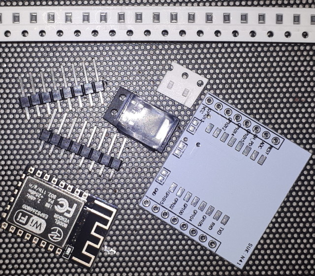
ESP12E or ESP12F MCU modules are not breadboard friendly. But there are adapter plates available that can be used to create a module that plugs into a breadboard or into a programmer. This description shows how to configure and use one of the available adapter plates. This description assumes that the device will be soldered by hand - much of the description of the construction is not relevant if soldering facilities for SMD are available.
Note: "ESP12" is a description often used for generic 8266 modules. The ESP12E and ESP12F are often lumped in with other ESP products, but they differ significantly from most other 8266 modules, both in form factor and how they are programmed. This description shows one way to deal with the issues of the form factor, and one way to make programming easy. The outcome is a very effective 8266 module at a very reasonable price.
Note: The difference between the ESP12E and the ESP12F is solely in the antenna design and tuning, and is not relevant to the procedure described here.

ESP12E or ESP12F Module
Adapter Plate. There are several varieties, but the one shown is the
cheapest and most common
2 x 10KΩ SMD resistors (included with the adapter, but see below)
2 x 8-pin headers (included with the adapter)
3.3V SMD regulator (optional - see below)
The adapter plate has pads for soldering the ESP12 and the two required resistors. It also includes pads on the rear for soldering a 3.3V regulator between VIN and VCC.
A suitable fixture for supporting the adapter on the work surface, and for holding the ESP12 firmly onto the adapter board is very strongly recommended. The tolerances are small and the ESP can be easily dislodged from its correct position. Small bulldog clips are very useful for holding the ESP onto the plate at the correct position.
Usual procedure would be to install the ESP last, in order to minimize the risk of damage when soldering the other parts. If the ESP and resistors are left to last then be very careful not to get any solder on the relevant pads when soldering the pin headers, as that will make positioning of the devices more difficult.
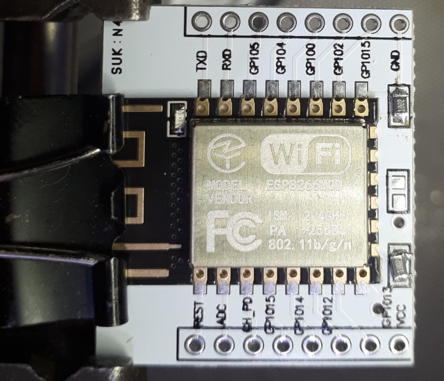
ESP12. Align the device carefully with the pads and clamp in place. Solder with a very fine tip iron and fine flux-cored solder. The solder pads on the ESP are carried down the sides of the scallops so there is good contact between the pads on the adapter and the module. However, it is difficult to confirm that the solder has run up the side properly, so it is worthwhile extending the soldering onto the top of the pads. The job looks neater without doing this, but it could save some difficult troubleshooting later on.
Note that the version of the adapter pictured here is the version that has the faulty labeling of pin #4 - the fourth from the top left. This pin is actually GPIO16. Pin #10 - second from the bottom right - is correctly labelled GPIO15, although it looks a bit like 13.

Resistors. The adapter is supplied with the two 10KΩ SMD resistors that are required for the 8266 to operate properly. The supplied resistors are 0402 size, and are extremely difficult to position and solder. The pads on the adapter easily accommodate 0603 size resistors, and these are much easier to solder by hand. However, be prepared to lose some resistors as they fly off at the slightest provocation and are unlikely to be found again on even the cleanest workbench. Surgical-style tweezers (press-to-open) make the job much easier. A good magnifier mounted above the fixture is a great help.
If the SMD devices are too small to solder then 1/4W resistors can be attached to the pads. Consider leaving the resistor leads long enough to fold the resistors under the board and out of the way. This option is quite suitable when the regulator is attached to the rear, providing attention is paid to placement.
The pads in the centre are for directly connecting the adapter VIN pin to the ESP VCC tab, for 3.3V breadboard power (see below).
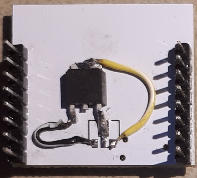
Power. The ESP12 is a 3.3V device. The adapter can be configured to work with either a 5V or 3.3V power supply.
For 3.3V breadboard power the centre pads on the front of the adapter are bridged. This links the VIN header pin of the adapter direct to the VCC pin on the ESP. A zero-ohm resistor is provided for this purpose, but it is much easier to just bridge the gap with a blob of solder.
For 5V breadboard power a regulator is required. The back of the adapter has pads for a SMD regulator: if it is installed the bridging pads on the front are left open and the output of the regulator is passed through to the VCC of the ESP. The layout supports MCP1703A or HT7333A with SOT-89 packaging. If it is difficult to find a regulator with the required form factor and a matching pin layout a different regulator can be glued to the adapter and wired to the pads. In this example a AS1117 with TO-252 packaging (Gnd/Out(tab)/In) has been used. It is the same height as the header pin supports (~2.2mm) so it does not interfere with the mounting of the adapter to the breadboard.
Powering the MCU from 5V through the regulator does not make the ESP12 5V tolerant! The ESP12 GPIO pins can be used to drive inputs of 5V devices (in most cases) but 5V devices should not attempt to drive inputs to the ESP12 unless the signal is routed through a level converter to drop the logic level from 5V to 3.3V.
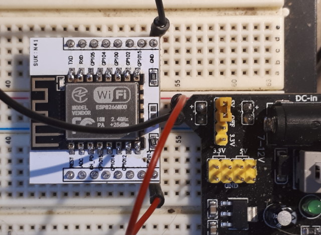
Headers. The headers can now be added. One option is to use standard female headers, so the fixture is used with the male programmer pins connected to the headers. An alternative is to use long-pin male headers and use the fixture with a breadboard. If using long-pin male headers be sure to set the pins into some alignment pieces to ensure they are straight - they are a long way apart and small errors in alignment can mean that they will be hard to press into a breadboard. Like most header pins, the supplied parts need to be carefully scraped clean (not just cleaned with a grease remover) in order for the solder to wick properly onto the pins. The board should be cleaned of all flux residue before use.
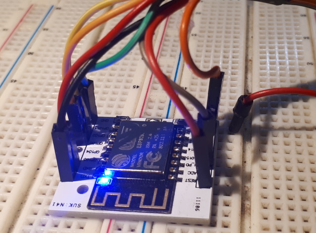
Usage. The module is now ready for use. Be sure to power it from 5V if the regulator is installed and the centre pads are left open, or 3.3V if the centre pads are bridged and there is no regulator.
Staking the module to the breadboard using male Dupont connectors is effective if care is taken. The ESP12 supports Over the Air (OTA) programming, so this arrangement should only be required to get a basic OTA sketc (blink is quite suitable) into memory. Once that is done all subsequent sketch uploads can be done through OTA.
For details on using the completed module with a custom fixture and serial programmer, see: ESP Adapter Plate Fixture
