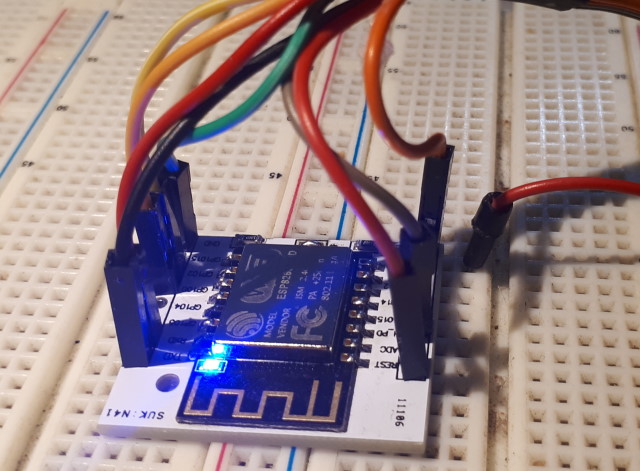
ESP32 and ESP8266 MCU development modules come in a wide variety of forms. Many of these modules include a programming interface. This is usually in the form of a USB port and associated components to enable the module to be plugged into the PC USB port and programmed using any suitable IDE. But some modules, designed to be as small as possible when implemented as a portable device, do not include the programming interface, and a separate programmer is required. Examples are ESP-CAM, ESP-01 series, ESP-07 series, ESP-12 series, and ESP-201.
Often the separate programmer only includes the communication part of the interface - control of the programming mode and the device restart is left to the user, with a series of steps needed to complete the task. There are many solutions available for creating the required interface, with varying degrees of convenience.
This project shows how one of the cheapest available programmers - for the ESP01 - can be used with a custom connecting cable to program any ESP device with the IDE taking care of the whole process of putting the MCU module into programming mode, downloading the code, and doing a reset, without any user intervention.
The programmer does several things, but not everything is provided on all programmers. Firstly it converts the 5V USB power to 3.3V. Secondly it provides a conversion from USB data transmission to UART (serial) data transmission. These two functions are essential. An optional function is to convert the DTR and RTS signals generated in the USB-to-Serial conversion into the required settings for the Enable and GPIO0 pins which change the mode of the ESP between program and run. Programmers that have this option do not require the insert/remove and reset procedures that put the ESP into flash mode and start the user application.
ESP01 programmer.
8 x M/F Dupont prototyping cables
8-pin (4x2) connector cover for Dupont female connectors (or 2x1x4, glued
together).
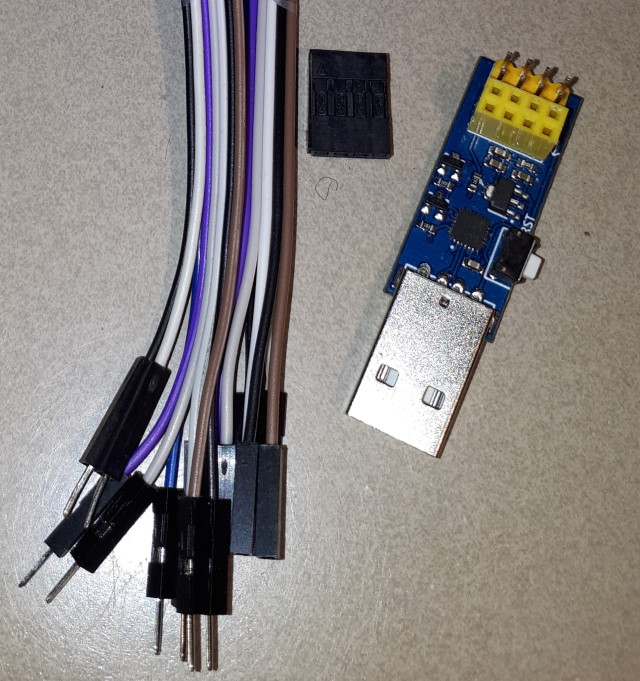
The 4x2 header socket is available from a number of sources, but is most commonly found in an old PC motherboard, perhaps as a socket to a backplane serial port, a backplane USB connection, or a front-panel switch and LED connection. It can be created from a 10x2 or larger by cutting away the unused portion. The programmer pictured here includes both male and female programming connectors. There are versions that are female only - that version can be used in exactly the same way as the one used for this project, except that the Dupont connectors will be M/M instead of M/F. However 2x4 pin connector covers for pins are not readily available for male connectors.
If possible, ensure that the Dupont cables are all different colours, as this will make the identification of each lead much easier.
Remove the individual connector covers from the female ends of the Dupont cables. The tip of a sharp blade is the best tool for lifting the tab so that the connector can be slid out. If using 2x1x4 connector covers glue them together back to back, so that the tabs are accessible for both sides. Insert each connector into place in the 2x8 connector cover, checking that the tabs push flat down and lock the connector securely.
Wire the cable onto the MCU module using the connection diagram below. Plug a USB cable into the connector, start up the IDE, identify the port and MCU device, and download the program. The device will be put into flash mode then restart at the end of the download, and the program will be running. For those modules without a reset connection the module will need to be manually reset after program download , either with a reset switch on the programmer or, if available, on the module.
To use the cable with modules other than ESP01 connect the separate female pins to a module mounted on a breadboard.
The image shows the programmer cable used with a ESP-12F mounted on a 0.1" adapter card with pins soldered. Note the resistors - these are for CH_PD to Vcc and GPIO15 to ground. (The link connects Vcc to 3.3V, bypassing the optional 5V to 3.3V regulator.)
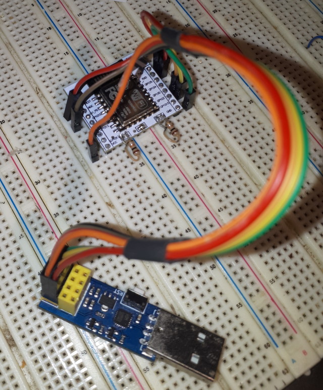

A third option (not shown) for when pins are not soldered into the ESP12E/F adapter is to solder flying leads instead, and attach Dupont pins to the end of each lead. Or, simply cut off one end of a Dupont lead and solder the cutoff end onto the module**. The ESP is then connected to the breadboard, or direct to the programmer, using the flying leads and the remaining M or F connector . Once the initial OTA sofware is loaded the flying leads can be cut to the correct length and the ESP installed in its final configuration. If the flying leads are custom-made then allowing sufficient length initially means that they can be used several times before they become too short to be practical.
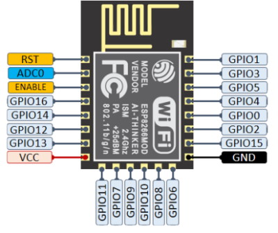
The programmer pin layout follows the ESP01 exactly, as the male headers are a copy of the female. The connections for other modules should be obvious, but unfortunately the ESP pins have multiple uses and multiple labels, and there is little consistency in which labels are used and even in the alternative label names.
Note that the pin numbering for headers does not follow the same style as is used for ICs and similar devices. The numbering starts at top left and alternates between the top and bottom rows. All the diagrams are shown as viewed from the top side.
| Programmer | ESP01 | ESP12x | ESP-CAM | Download (Programming) Mode* | Running Mode* | Image |
| 1 GND | GND | GND | GND | Ground | Ground | Green |
| 2 GPIO1 | TXD | GPIO1-TXD0 TX | GPIO1 U0TXD | Black | ||
| 3 GPIO2 | IO2 | GPIO2-TXD1 D4 | GPIO2 HS2_DATA0 | High | High | Yellow |
| 4 CH/EN | EN | CH_PD ENABLE | High |
High | Grey | |
| 5 GPIO0 | IO0 | GPIO0-FLASH D3 | GPIO0 CSI_MCLK | Low | High | Pink |
| 6 Reset | RST | RST | High | High | Red | |
| 7 GPIO3 | RXD | GPIO3-RXD0 RX | GPIO3 U0RXD | Red | ||
| 8 VCC | VCC 3V3 | VCC 3.3V 3V3 | 3.3V/5V | 3.3V | 3.3V | Orange |
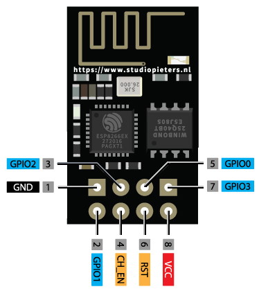
* Low means tied to ground, High means tied to 3.3V, in each case through a 10kOhm resistor. If the programmer does not manipulate the GPI0 and/or Reset pins automatically then a switch must be added to these pins. Similarly, some programmers may require the module to be disconnected in order to reset. Resistors may need to be added to tie Enable high and GPIO15 low, depending on the module.
** Note that some cheaper 'Dupont' flying leads use copper-coated
aluminium wire. This is almost impossible to solder and would not be
suitable for this application. Check before committing to this
option.
