 16
small springs. The ones used here are flat, about 8mm extended and 6mm
compressed, with a protruding tab at one end and solder tail at the other.
See below.
16
small springs. The ones used here are flat, about 8mm extended and 6mm
compressed, with a protruding tab at one end and solder tail at the other.
See below.3D printed base
2 x 8-pin female headers
Piece of perfboard
A fixture for temporary mounting of an ESP12 on an adapter plate, for programming, without the use of header pins.
This project demonstrate the construction and use of a fixture plate that can hold an ESP12 MCU for connection to a serial programmer. The fixture is required for cases where the eventual installation of the ESP12 in a project will be direct wired to the adapter plate, and therefore the header pins will not be installed. This allows a much smaller installation than is otherwise possible.
The fixture allows the ESP12, as attached to the plate, to sit on a series of springs which in turn are connected to a header, which can accept the pins from a serial programmer. Once programmed, the ESP12 and adapter are simply lifted off the fixture, flying leads soldered to the thru-holes on the plate, and the assembly mounted in the project.
It is unlikely that the exact construction details used here could be followed for other constructors, but the idea can be adapted to available materials. See Version 2, below, for a different option.
Update: There is at least one other version of the adapter plate with thru-holes that are smaller than the holes in the sample used her. These plates will not work with the spring version of the fixture, as the holes are too small and inserting and removing the plate damages the springs. However they work very well with the 1mm pin version (Version 2 - below) as the smaller holes are a very neat fit to the pins.
16
small springs. The ones used here are flat, about 8mm extended and 6mm
compressed, with a protruding tab at one end and solder tail at the other.
See below.
3D printed base
2 x 8-pin female headers
Piece of perfboard
To avoid running wires on the underside of the perfboard, there should be two rows of at least three connected holes arranged so that the holes in the adapter sit at the inner end of each set of three, and the headers wil sit at the other end.
 The
spring was sourced from the bits box, so it is uncertain where it
originated. Considering the number involved, it was likely a print
head and probably an inkjet cartridge mounting plate.
The
spring was sourced from the bits box, so it is uncertain where it
originated. Considering the number involved, it was likely a print
head and probably an inkjet cartridge mounting plate.
The important features are that it is a flat spring, it has a tab at one end that suits the size of the hole in the adapter, and it has a solder tail.
The 3D-pinted fixture was constructed with slots to match the width and height of the spring, so that the shoulder would protrude about 1mm, allowing room for the adapter plate to compress the spring very slightly. A flat spring was selected because of the small amount of room available between solder holes on the adapter. A 3D printer with very high resolution may be able to accommodate a round spring.
The tab is a loose fit into the solder hole on the adapter, so it is likely that the primary electrical contact is between the rim of the solder hole and the first leaf of the spring. If the tab on the spring is a neat fit in the solder hole the current design would not work, because the adapter could not be removed without risk of damaging the spring - a design that safely retained the spring near the top, not just by the solder tab at the base, would be required.
.
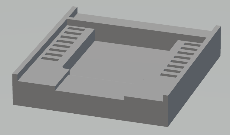
The base for the fixture, as designed. Slots to match the springs are set down either side, with rails on three sides that the adapter can be positioned against. There is a hollow in the middle in case a regulator has been mounted on the rear of the adapter. The top side was left open to facilitate removing the plate, but it turns out that the springs lift the plate off the base sufficiently so that removing it is not a problem.

The printed base is screwed to the perfboard from below, and the springs inserted and soldered to traces on the underside. The whole assembly is arranged on the perfboard so that the trace for each spring comes out to a solder hole just outside the edge of the base. The headers can then be soldered in a row for each set of springs.
It is apparent from this photo that the tabs of the springs are not evenly spaced along the length of each row. This is because the slots in the base were made somewhat wider than the springs, and this in turn was because of uncertainty about the ability of the printer to create a base with very thin slots.
The result is that a certain amount of fiddling is required to get the tabs of the springs into the holes in the adapter when mounting it. The current workflow relies on OTA programming for the ESP12, so the fixture is only required once for each unit. It may be that the capability of the printer was underrated, and if the workflow requirements change it would be worthwhile experimenting to see how thin the slots can be made, and still be usable, in order to get the tabs spaced more evenly.

The fixture plate as used in programming an ESP. No provision was made for pressing the adapter down onto the springs, and it turns out it is not required. This may be because the weight of the MCU and adapter is sufficient to level out the springs, or it may be that the contact between the tabs and the interior of the adapter holes, though very light, is sufficient for the very small currents involved.
If contact is a problem then for the brief time needed to execute the
programming, simply pressing with a finger would be quite practical, or
perhaps a small weight to sit on top. Otherwise, a flexible bar that
hooked under the ends of the perfboard would be very effective. The
perfboard should have a standoff added at each corner.
When using the adapter plate fixture for programming it became clear that
it was not necessary to have the ESP12 pushed down against the springs of
the contact pins. Programming and debugging was effective with the
MCU simply sitting onto the tabs. This raised the question of
whether an alternate arrangement that did not require the springs was
possible. This would make the insertion and removal of the MCU somewhat
easier.
 The
pins of a male DB25 connector are a neat fit in the solder holes of the
adapter plate. The shanks of the pins can be made to fit into the
solder holes of the protoboard if the holes are drilled out with a 1.5mm
bit. The adapter plate can be used as a template to ensure that the pins
are properly aligned as they are soldered. This alternative turns
out to be nearly as effective as the original design. There is no
reason to suspect that the pins will wear and lose contact.
The
pins of a male DB25 connector are a neat fit in the solder holes of the
adapter plate. The shanks of the pins can be made to fit into the
solder holes of the protoboard if the holes are drilled out with a 1.5mm
bit. The adapter plate can be used as a template to ensure that the pins
are properly aligned as they are soldered. This alternative turns
out to be nearly as effective as the original design. There is no
reason to suspect that the pins will wear and lose contact.
The male DB25 connector is disassembled so that the pins can be extracted by drilling out the rivets of the mounting holes and separating the two halves of the shell and the insert.
 The
prototype shown here was built on two separate pieces of perfboard because
it was not possible to find one piece with a suitable arrangement of
connected pads the right distance apart for the header - a single piece of
perfboard would probably be simpler, but two separate pieces does provide
some flexibility during insertion and removal of the adapter plate.
This example uses female headers for direct connection of the programming
cable - the alternative is to use long-pin male headers for use with a
breadboard.
The
prototype shown here was built on two separate pieces of perfboard because
it was not possible to find one piece with a suitable arrangement of
connected pads the right distance apart for the header - a single piece of
perfboard would probably be simpler, but two separate pieces does provide
some flexibility during insertion and removal of the adapter plate.
This example uses female headers for direct connection of the programming
cable - the alternative is to use long-pin male headers for use with a
breadboard.
The result has been the reverse of expectation! The original version worked perfectly with the adapter plate just sitting on the tabs of the springs. This would be very light contact, but it was quite reliable. In the second version the adapter slides quite firmly onto the pins, and the expectation was that there would be good electrical contact, with the relatively large surface area of the inside of the plated thru-hole as the available contact area. But in practice, pressure on the plate is required to ensure good contact with the pins. Presumably, the pin alignment is sufficiently inaccurate to prevent some pins from contacting their holes. If the pressure is maintained then this version is completely satisfactory, but without the pressure electrical contact can be incomplete.
Given that the DBxx-connector male pins are much more accessible than the springs used in Version 1, this alternative may be a better proposition than the original, with the caveat about requiring pressure in order to maintain adequate contact.
