GPS Digital Clock
A project to create a simple digital clock using a GPS receiver as the
source for the time. The point of the project was mainly to find a use for
a very old GPS receiver and one of several TFT touch screens that were
originally sourced for other projects. Becausue it uses the GPS signal for
synchronization it is accurate to the second whilever the GPS signal is
available.
Parts
 Arduino
UNO. Standard format, but the exact variant doesn't matter. However
some are easier to use than others - see comments below.
TFT Touch Screen 320x240. This is the type that has a row of
pre-printed button icons in an additional strip across the bottom (or down
the side, as used in this project).
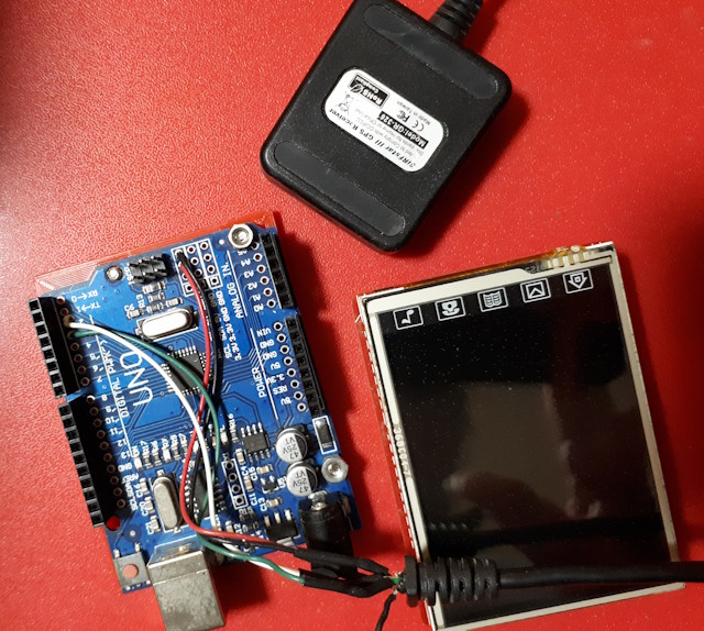
GPS receiver with 5v serial output. This project uses a
SiRF-Star III because it was available. It is a 'puck' style on a
long lead which enables it to be placed conveniently for a good view of
the satellites. It is not necessary to have the latest available model,
but it should be configurable for message selection, message rate and baud
rate).
Construction
 The UNO
supports a single serial port on D0, D1. However this port is used for
programming and is driven though the USB interface, and is inconvenient to
use for other devices. So the project uses a software serial port
for the GPS interface. The problem is that the TFT touch screen is a
shield that connects to all the UNO pins, even though it doesn't use them
all - D2, D3 are available for a serial device, but making a connection to
them can be difficult.
The UNO chosen for this project provides a row of solder points for pins
or wires alongside both strips of headers, as well as a small prototyping
area. This makes attachment of other devices in addition to
the TFT shield very simple. The GPS receiver is wired to the pads for D2,
D3, 5v and Gnd (see image above).
The alternative is to wire to the bottom of the UNO board, which is
tricky, or to use a breakout
board inserted between the UNO and the TFT shield.
Note: If the breakout is used it is important to check
whether the shield uses the ISP header on the UNO. The reason that
the shield might use this header, even though it only duplicates pins
already available elsewhere, is to make it compatible with the MEGA 2560,
which uses different pins for ISP. If the shield uses the header
then it must be provided on the breakout. It is not necessary to use a
long-tail header - a simple 2x3 header can be used if it is wired across
the bottom of the breakout to the appropriate pins for a UNO.
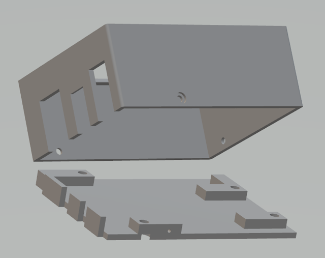
A simple 3D-printed case is used to house the clock. For
this project the base was built up only to the underside of the UNO PCB,
and the lid extends down to the bottom of the base. The lid is
secured by three small screws through the side, into the pads that support
the UNO. A nice addition to the case would be a holder for the
stylus. The case interior can be lined with black vinyl tape
to suppress the light from the module LEDs that otherwise bleeds through
the plastic.

The GPS receiver must be set up for the messages (only RMC is used), the
message interval (1s) and the baud rate (4800 in this case). Some
example GPS initialisation code is included. As this is a very
old GPS receiver it was simplest to select the update rate and baud rate
that the device defaulted to. A faster baud rate (up to about 19200)
would be preferable, and initialisation code to support a specific GPS
receiver could be used (an example is included). However, note that
software serial has a limitation on the maximum speed that is relaibly
supported. At a rate of 4800Bd and only receiving RMC messages once
per second the display can nearly keep up with the time - a second is
skipped about once every couple of minutes.
Software
 The software is more complex than might be imagined, mainly because of the
need to keep screen updating to a minimum. This is achieved by
only updating what has changed - seconds every second, minutes every
minute and so on. When updating the hour the date is also updated in
case it also changed. (Note that the date needs to be checked every hour
because the GPS day could change at any hour, depending on the UTC
offset.).
The other complexity is the synchronization between the GPS time and the
internal counter. Because the time and date data from the GPS may
become unavailable for periods it is necessary to check whether GPS time
or an internally calculated time should be used. The procedure
implemented in this code is to assume that the internal counter should be
used first, then check if it needs to be updated with a valid GPS signal.
However the code will not start until the first character of the first
message from the GPS receiver is ready.
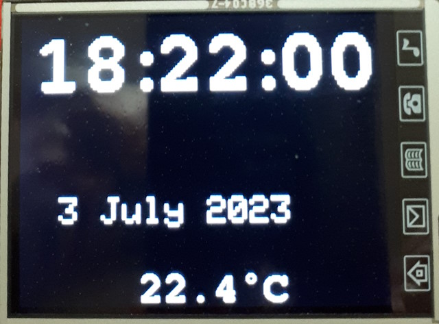
The local day and date is calculated using routines from the TimeLib
library. Note that the attached images might not show the day of the week.
The software footprint is about 27000 bytes or a bit less than 85% of
program storage space - about the practical limit for a UNO. Global
variables use about 1200 bytes or 63% of dynamic memory.
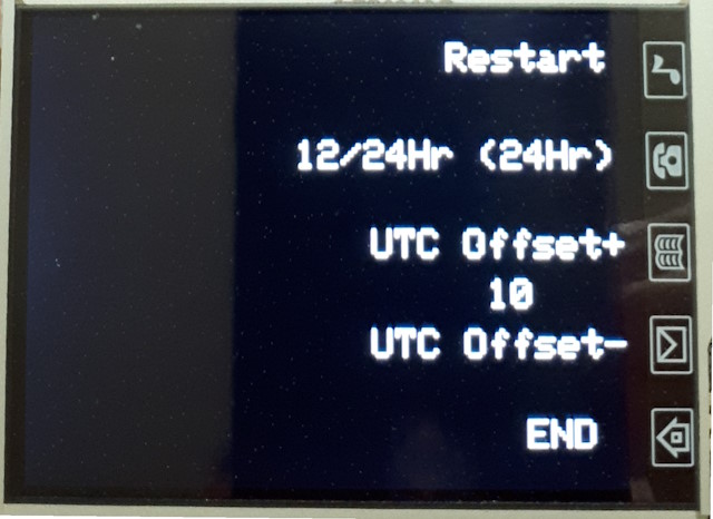
The touch pads at the right of the screen are used to open the user menu
and then provide options to reboot, select 12- or 24-hour format,
increment UTC offset, and decrement UTC offset. The home symbol is used to
open and close the user menu. Time format and UTC offset are stored in
EEPROM. UTC Offset is only supported for 1-hour increments -
changing this to 1/2-hour would require very little additional code, but
would make selection slower for most users.
The seconds update is not regular and updates are sometimes missed. This
is because the UNO cannot quite keep up with all the things that need to
happen when the GPS message is received, especially at 4800bd. Each
message is first checked to be sure it is a RMC, then the CRC is checked
and finally it is parsed to extract the time and date values. If any
time value is changed then the changed values are updated, and in the case
of an hour change the date is also recalculated and displayed. The
validity checking of the received GPS data is very thorough and devices
that do not quite conform to the standard might fail.

The user menu is accessed with the 'Home' icon in the lower right corner
and the options use the other icons. They are labelled as the icons don't
have any significance. The button facility of the GFX library is not used,
and the button locations are hard-coded. Note that for this
procedure to work correctly the screen calibration data must be
entered. If this is not available from a calibration routine it can
be worked out by removing the mapping function in the Touch_getXY function
and displaying the raw touch data on the console. Note that the
names used for the mapping variables do not make sense for a landscape
orientation - they have been left like this in order to be consistent with
the way they are reported in the TFT touch screen calibration
example sketch used for these displays.
The temperature is displayed whenever it changes. Note that this is
never correct because the sensor is buried in the middle of the two
modules and gets significant warming from the devices, especially the
display lighting. A small heatsink connected to a metal pad on the
base of the case would improve the temperature reading somewhat but would
be difficult to arrange.
The code uses a
custom font for the time and temperature display, because the
default font looks awful when expanded to the required size. The UNO
memory is not sufficient to support a complete font at this size, so it is
restricted to 0 to 9, A, C, M, P full stop and degree symbol. Note
that the font file and most of the libraries (including the
dependent GFX library) are referenced from a subfolder 'src\' in the
sketch folder.This means they will not change as a result of updates once
the program has been confirmed as working.

This page last updated 18th August 2024

 Arduino
UNO. Standard format, but the exact variant doesn't matter. However
some are easier to use than others - see comments below.
 The UNO
supports a single serial port on D0, D1. However this port is used for
programming and is driven though the USB interface, and is inconvenient to
use for other devices. So the project uses a software serial port
for the GPS interface. The problem is that the TFT touch screen is a
shield that connects to all the UNO pins, even though it doesn't use them
all - D2, D3 are available for a serial device, but making a connection to
them can be difficult.
 The software is more complex than might be imagined, mainly because of the
need to keep screen updating to a minimum. This is achieved by
only updating what has changed - seconds every second, minutes every
minute and so on. When updating the hour the date is also updated in
case it also changed. (Note that the date needs to be checked every hour
because the GPS day could change at any hour, depending on the UTC
offset.).
