TFT Shield Adapter
This is a small project to create an adapter to use with the Arduino UNO
and the TFT shield. The adapter allows serial data to be streamed to
the display, with or without formatting for special purposes.
 The
adapter is needed because the TFT shield covers all the UNO GPIO
headers. This means that those GPIO pins that are available
for some other use are not accessible, so the TFT shield cannot be used
with any other components, such as sensors. Examples of usage
are displaying the data from a GPS receiver, a serial port monitor, or a
debug assistant when debugging devices that do not support output to the
IDE console, such as a MCU in OTA mode, or devices that use CDC for the
USB interface, such as ESP32-C3 Mini.
Although the shield covers all the UNO headers, it does not use all the
pins. This particular shield does not use digital pins 0,1,2,3 and
analog 4,5. Also, pin 12 is available if not using the micro SD. Of
course, the ground and power pins can be shared with other devices.
So it is useful if these pins (or some of them) can be brought out to
headers on an adapter. In this example I have chosen to bring
out D0, D1, D2 and D3 which seems to cover the pins that are usually
available. A4, A5, if available, can be used for special purposes, as
described below. Also brought out are +5v, +3.3v and two Gnd.
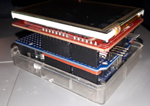
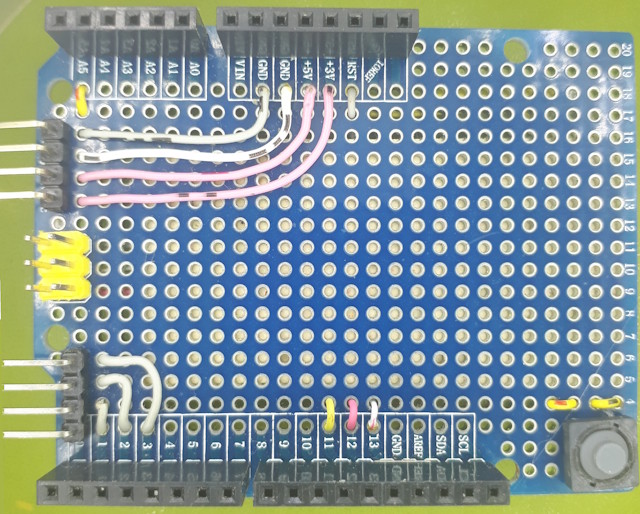
 The
adapter is built from a prototyping board that supports double stacking.
Long-pin female headers are installed as usual to provide the through
connections for the TFT, and two 4-pin, 90-degree male headers are
installed at the end of the board for the external
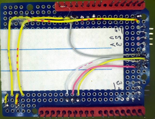
connections. Wiring is then run from the 90-degree headers to
the corresponding points on the prototyping board.
This project mounted the headers to the last row of the prototyping
board, providing a total of 8 pins using two 4-pin headers. There
are more spaces available on this row, but using them creates some issues:
they will interfere with the ICSP header, they might interfere with the
mounting holes, and D0 (Rx) is the last hole on the end row and can't be
used for anything else. These problems could be overcome, and
a total of 11 pins brought out, if the headers are set back from the end
by a row or two. This makes the connector pins slightly less
accessible. An additional 4 pins are available in the end row if
access to the ICSP header is not going to cause a problem. This example
includes the ICSP header, so there was no room for extra pins. A5 was
wired as a reset button and A4 was not wired.
 The UNO attached to the display is coded with a routine to simply send
text received at the serial port to the display. This example
included code to clear the display when the button attached to A5 was
pressed. Other options are to count characters and clear
the display when the screen is full, include code to detect a
'clear-screen' command sequence, or count characters and scroll the whole
screen as required.
Some precautions are required for using the serial port:
- Software Serial is required if using 2,3 as the serial I/O
- If using 0,1 then the USB connector to the UNO should be removed, or a
USB lead used which does not have data lines - ie a power-only lead.
Also, with two MCUs connected together it is important that :
- a ground connection between the two devices is established before
anything else is connected, and
- both devices have power before any data line is connected.
This page last updated 27 March 2025

 The
adapter is needed because the TFT shield covers all the UNO GPIO
headers. This means that those GPIO pins that are available
for some other use are not accessible, so the TFT shield cannot be used
with any other components, such as sensors. Examples of usage
are displaying the data from a GPS receiver, a serial port monitor, or a
debug assistant when debugging devices that do not support output to the
IDE console, such as a MCU in OTA mode, or devices that use CDC for the
USB interface, such as ESP32-C3 Mini.
 The
adapter is built from a prototyping board that supports double stacking.
Long-pin female headers are installed as usual to provide the through
connections for the TFT, and two 4-pin, 90-degree male headers are
installed at the end of the board for the external
connections. Wiring is then run from the 90-degree headers to
the corresponding points on the prototyping board.
  The UNO attached to the display is coded with a routine to simply send
text received at the serial port to the display. This example
included code to clear the display when the button attached to A5 was
pressed. Other options are to count characters and clear
the display when the screen is full, include code to detect a
'clear-screen' command sequence, or count characters and scroll the whole
screen as required.