The DHT11 humidity and temperature sensor is available as Keyes module KY-015. This module provides single-wire communication to the HT11. It can be paired with an ESP01 to make up a humidity sensor for a 3D printer filament container that displays the current humidity to a web page on the local WiFi network. It will be used in this example to provide monitoring of the humidity from within the closed filament container of a 3D printer.
This project combines two challenges:
- Get the KY-015 module connected to the ESP01, considering
the limited number of GPIO ports that the MCU exposes
- Implement OTA updating, alongside the application
OTA or Over The Air updating is a mechanism that uses the WiFi connection of the MCU to enable updating the MCU firmware over the local WiFi network when there is no physical access to the device. It is relevant to this application because the humidity monitor will be inside the closed filament case. Installing OTA means that the code can be updated without opening the case.
OTA works by enclosing the application code in a 'wrapper' of OTA client code. The wrapper supports upgrading of the application software from an OTA server. Each upgrade includes the application software inside the OTA wrapper, so it is ready for future upgrades. For this project the OTA server will be the Arduino IDE: other options for doing the upgrade, such as from a browser, require a different wrapper. As this application requires WiFi communication for both the firmware upgrading and for the application execution it could only be implemented with other OTA servers that support a mixture of protocols.
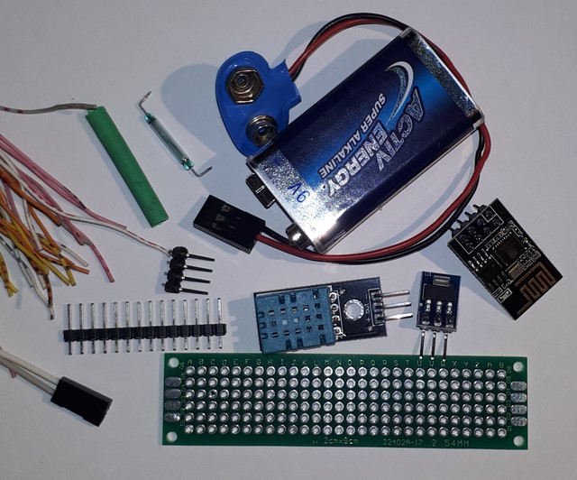
- ESP01 8266 MCU Module. This should be a 1Mb or 4Mb
flash memory version - the 512kB version will not work due to the code
size. Other 8266 devices can be used, but part of the purpose of this
project was to see how much functionality can be extracted from the
minimalist ESP01.
- KY-015
Humidity and Temperature Sensor. This is a 3-pin module for the
DHT11. It adds a 10k pullup resistor to the HT11 signal line.
The HT11 could be used instead of the module if a similar pullup resistor
is added. The value is not critical and anything from 3.3kOhm to 12kOhm
would be suitable.
- AMS1117 3.3V regulator module.
- 9v alkaline battery. A suitable rechargeable battery could also be
used. The case needs to be opened occasionally to change spools and
refresh the silica gel, and this should roughly correspond to battery
recharging or replacement.
- Battery connector
- Prototyping board. This example used a long slim board with the modules
laid out in a line, but the arrangement is not critical
- Female headers - 2x4-pin (ESP-01), 1x3-pin (Sensor)
- Straight male headers. (SPI (4), UART (2), PWR (2) plus several more for
extra stability.
- 90-degree headers - 1x2-pin (Battery)
- M/F 2-wire Dupont cable
- Reed switch
- Hookup wire, heat shrink
A programmer for the ESP01 is also required for initial setup. A programming module is by far the easiest, but as it is only used once the alternatives of an Arduino or ESP (such as a Node MCU) set up as a USB-to-serial converter, or any other form of serial converter, could also be used.
This example will use a reed switch and magnet to turn the module on and off from outside the container. However a switch of the type that inserts into a hole drilled into the case would work as well.
 The
ESP01 requires a specific configuration for programming via UART - see ESP Programming Cable Project. However, programming
via OTA does not require any change from the standard operating
configuration for the ESP01. This means that the configuration for a
minimal system is:
The
ESP01 requires a specific configuration for programming via UART - see ESP Programming Cable Project. However, programming
via OTA does not require any change from the standard operating
configuration for the ESP01. This means that the configuration for a
minimal system is:
ESP01
Pin 1 - UTXD KY-015 Signal (GPIO1)
Pin 2 - Ground
Pin 3 - CH_PD/ Enable (10K resistor to Vcc)
Pin 4 - GPIO2 NC (internal pullup)
Pin 5 - RST NC (10K resistor to Vcc is recommended, but seems unnecessary)
Pin 6 - GPIO0 NC (internal pullup)
Pin 7 - VCC 3.0V~3.6V
Pin 8 - URXD NC
KY015
Pin 1 ESP01 TX
Pin 2 VCC 3.0V~5.0V
Pin 3 Ground
Note that pin numbering for the ESP01 module can vary - some diagrams use
the format of a DIL IC (anticlockwise around the circumference) while
others use the format of a connector (left to right, alternating between
rows). This description has followed the common practice for a 4x2
header.
The use of ESP01 TX (GPIO01) pin is arbitrary, however some of the other ESP01 GPIO pins have a special meaning at boot time and may cause problems if used for devices. Using TX does mean that the console cannot be used for debugging during development. For that reason it is recommended that initial development is carried out using another GPIO pin for the KY-015 signal, and using a programmer to take care of the signal levels that control boot mode (program or execute) and reset. An option that does support limited debugging is to use RX (GPIO3) and configure the Serial device to be 'send only'. However the best option is to start with the device configured with OTA, and use OTA throughout.
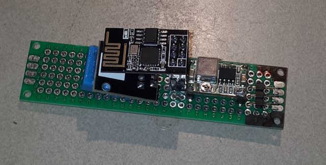 The
components are assembled on a scrap of prototyping board, in order of
battery connector, regulator, ESP-01 and sensor. The layout is
arranged so that the supply rails are (nearly) aligned. The wiring
is on the back and the front, to keep ground and Vcc separate as far as
possible. Both the KY-015 and the ESP-01 are socketed: necessary in
the case of the ESP as a mistake during OTA programming could require it
to be removed and reprogrammed with a wired connection. The
regulator is soldered onto the protoboard. The reed switch is installed in
line in the positive lead of the Dupont cable connecting the battery to
the board. It could be mounted on the board, provided that
when installed it is close enough to the wall of the container to reliably
operate with a magnet positioned outside. Installing it in the cable
allows for a variety of mounting options.
The
components are assembled on a scrap of prototyping board, in order of
battery connector, regulator, ESP-01 and sensor. The layout is
arranged so that the supply rails are (nearly) aligned. The wiring
is on the back and the front, to keep ground and Vcc separate as far as
possible. Both the KY-015 and the ESP-01 are socketed: necessary in
the case of the ESP as a mistake during OTA programming could require it
to be removed and reprogrammed with a wired connection. The
regulator is soldered onto the protoboard. The reed switch is installed in
line in the positive lead of the Dupont cable connecting the battery to
the board. It could be mounted on the board, provided that
when installed it is close enough to the wall of the container to reliably
operate with a magnet positioned outside. Installing it in the cable
allows for a variety of mounting options.
Mounting requirements for the sensor are quite flexible, with things like airflow, direct sunlight and other sources of heat being the only considerations. Only airflow is relevant in this application, so the sensor is mounted a small distance off the surface of the board.
Note: When running the hookup wiring on the protoboard it is very easy to get confused about which way around the ESP-01 and the sensor module are oriented in their sockets. One useful shortcut is to mark the Vcc and Ground points on both sides of the board with red and black permanent marker pen before starting. This provides a reference against which the other connection points can be located. But even with this assistance it is important to repeatedly check that the pins are being identified correctly.
Note: The TX/RX markings on the controller cannot be relied on. For some controllers TX means 'This is the transmit signal" and for others it means "Connect this pin to your device transmit pin". Be prepared to test the controller with a cable link that allows you to swap TX and Rx to get it right.

This application also included a 3D-printed case with voltage supply readout for the battery. The case has no back so that there is sufficient airflow around the sensor. The battery voltage display also functions as a 'power on' indicator, because the LEDs on the regulator and ESP-01 are not visible when it is in a case. There is no reason that the protoboard could not be mounted directly on the wall of the container so that the LEDs would be visible.
 The
device is installed in the filament box with the battery sitting in the
bottom of the box. The reed switch is placed between the
spool-holder axle and the back of the container, so that a magnet can be
simply held against it, or hung from the top of the outside of the
container to turn it on and off. The silica-gel containers sit in the
bottom of the box.
The
device is installed in the filament box with the battery sitting in the
bottom of the box. The reed switch is placed between the
spool-holder axle and the back of the container, so that a magnet can be
simply held against it, or hung from the top of the outside of the
container to turn it on and off. The silica-gel containers sit in the
bottom of the box.
The code example uses the simplest possible arrangement - the ESP01 is a WiFi client (Station Mode) on the LAN, and the returned result is a web page. An alternative is to establish the ESP in Access Point mode with an assigned URL - this has the advantage of a permanent address so that a link can be created. However most routers allow assigning permanent addresses based on MAC address, so it is also possible to create a shortcut to a fixed address when in Station Mode. The WiFi client URL assigned at startup is displayed on the console, if attached, but can also be discovered using the admin utility in the WiFi modem/router, under a heading such as 'Attached Devices'.
This code uses the ADAFruit sensor library for interrogating the DHT11 - other libraries are available, or there is code available to bit-bang it. In this case there is ample memory in the ESP01, so the library is the simplest way to go. The web page has been configured to suit both a PC and a phone display. Debuggin statements have been included - they do not interfere with the operation of the device, but can be removed.
