
This is a description of a wired remote controller for a CNC engraving machine using a touch-screen TFT-LCD display and an Arduino Mega2560.
It is usable with any 3-axis CNC machine that supports a serial interface
port and which is running GRBL version 1.1 or higher*. The
controller has options to jog the machine on 3 axes, to turn the spindle
motor (or laser) on and off, and to issue some GRBL control commands.
Parameters settings for jog distance and spindle speed (if supported) are
also provided.
* Version 1.1 of GRBL is the first version that supports jogging (as
distinct from simply moving the axis with G commands).
The project was constructed as a wired controller using 5V UART serial communication at 115200 baud. It could easily be expanded to an unwired controller using a pair of NRF24L01 modules, a pair of ESP8266/32 using ESP_NOW, or equivalent.
Arduino Mega 2560 (a UNO does not have sufficient memory for the
software).
TFT/LCD 320x240 Touch-screen display module.
SD-Card module with SD card.
8-core ribbon cable with 2 of 2x4P IDC female connector and 1 of 2x4P
PCB-mount male connector.
Prototyping board (trimmed to size).
Miniature momentary PB switch (required only if the CNC controller
supports the extra function).
0.1" Header pins (for connecting the protoboard to the Mega).
Hookup wire.
The momentary push-button switch is optional if the controller does not support it or if the same function is already available at the controller.
Note that the display module must be 5V compliant to work safely with the Mega. Not all sellers make this clear and some are advertised as 5V devices even though they do not have the required logic level converters. If it is not specified in the description a very reliable way to tell is to examine the image of the underside - if there is a pair of multi-pin ICs side by side it is a good bet that they are the logic level converters and the device is fully 5V compliant.
The TFT Display used in this example project included a SD card reader, but it cannot be used with the Mega, so a separate module has been specified. The software includes a function to send gCode files stored on the SD card to the CNC device.
Soldering iron with a fine pointed tip, and some solder
Soldering fixture with light and magnifier
The TFT-LCD touch screen plugs directly into the Mega, but it covers a lot of the pins, so the way in which the required pins are accessed needs to be considered.
The controller connection requires 5V and Ground to power the Mega from the controller, and TX/RX for communication. If the CNC controller supports other functions then one or two digital I/O signals could also be implemented, and these would need to be broken out. The TFT-LCD shield covers the usual ground and UART pins.
Although the displays differ in how many of the Mega pins they actually use, they all cover the entire UNO footprint, leaving only the additional Mega pins available, unless special provision is made.
One option is to use a UNO-format prototyping board placed between the MEGA and the display, and break out the required pins to connections on the end of that board. The breakout can be either to solder points, header pins, or a socket for the cable. This option requires additional components to mount the SD-Card and cable socket, but may be suitable if the additional height is required for other components, such as a switch.
 Uno-format
prototyping board inserted between the Mega and the display shield, with
the required pins brought out to angled headers. Note the spacer under the
proto-board - this is required for correct alignment because the long-leg
headers are soldered from below so they do not have the spacer that comes
with pins that are soldered from the top.
Uno-format
prototyping board inserted between the Mega and the display shield, with
the required pins brought out to angled headers. Note the spacer under the
proto-board - this is required for correct alignment because the long-leg
headers are soldered from below so they do not have the spacer that comes
with pins that are soldered from the top.
The preferred option is to use the Mega pins that are exposed beyond the end of the shield. These pins can be connected with male header pins mounted on an adapter board to attach it to the Mega. The adapter will also carry the SD-Card reader (if installed) and the cable header.
The UART connection can be provided at TX1/RX1 by coding the serial device as Serial1, which is pins 18 and 19. Gnd is available below pins 52/53, and 5V is above pins 22/23. The SD card uses the Mega SPI pins at 50/51/52 plus CS which is assigned in software to pin 53 for this application.The adapter can plug into several unused Mega pins to provide stability. If additional functionality is to be implemented via the controller connector (such as Reset) then a signal can be provided from any of the GPIO pins 22 to 49. Note that the adapter and SD module will cover the Mega reset button - several models of the TFT/LCD shield include a reset switch, which is actually more accessible than the Mega switch, especially if the whole device is enclosed in a case. Otherwise, Mega reset should be brought out to a momentary PB switch mounted on the side of the case. General
layout of components: Mega and display shield with proto board providing
connections to 5V, Gnd and UART1, a 2x4P male connector for the cable, and
the SD-Card module. A small pad, such as double-sided adhesive
foam, is required underneath the SD-Card module to keep it
level. A switch is shown, which could be used to control the
additional wired function on the CNC controller, if provided, or a Mega
reset if there is not a reset button on the TFT module. However the
height available for a switch is limited, and the software mentioned below
is easily extended to include a touch button for that function. The pins
for the switch used in this example are not on a 0.1" spacing, so it
was easier to mount it with only two pins soldered to the board, and the
leads connected to the other two pins.
General
layout of components: Mega and display shield with proto board providing
connections to 5V, Gnd and UART1, a 2x4P male connector for the cable, and
the SD-Card module. A small pad, such as double-sided adhesive
foam, is required underneath the SD-Card module to keep it
level. A switch is shown, which could be used to control the
additional wired function on the CNC controller, if provided, or a Mega
reset if there is not a reset button on the TFT module. However the
height available for a switch is limited, and the software mentioned below
is easily extended to include a touch button for that function. The pins
for the switch used in this example are not on a 0.1" spacing, so it
was easier to mount it with only two pins soldered to the board, and the
leads connected to the other two pins.
The prototyping board has been trimmed to fit - see Protoboard Table Saw. A small button was 3D-printed for the Arduino Reset that is brought out to the display. A lip on the button and a recess in the lid keeps the button upright.
 The
Mega is mounted in a standard 3D-printed 2560 base with a custom-designed
lid. The SD-Card reader, cable socket and PB switch are soldered to
the protoboard, and male headers soldered underneath to match the required
Mega connections, plus some others (not connected) for stability.
The board is then plugged into the Mega. This puts the protoboard
and the display PCB at the same level. Note that the protoboard
should be trimmed to fit against the side of the TFT display, and within
the boundaries of the board (including any intrusions used for screw
mounts in the corners). The board wiring can be a combination of top
and bottom, in order to route the hookup wire in the most convenient
manner. As the board and its components are a separate module, all the
wiring can be done with the proto board on the bench.
The
Mega is mounted in a standard 3D-printed 2560 base with a custom-designed
lid. The SD-Card reader, cable socket and PB switch are soldered to
the protoboard, and male headers soldered underneath to match the required
Mega connections, plus some others (not connected) for stability.
The board is then plugged into the Mega. This puts the protoboard
and the display PCB at the same level. Note that the protoboard
should be trimmed to fit against the side of the TFT display, and within
the boundaries of the board (including any intrusions used for screw
mounts in the corners). The board wiring can be a combination of top
and bottom, in order to route the hookup wire in the most convenient
manner. As the board and its components are a separate module, all the
wiring can be done with the proto board on the bench.
The cable is connected straight through: ie pin1 to pin1. Below is an
example of the pinout for a controller board, looking down on the male
header. This seems to be standard for controllers that support this type
of interface.
__________________
|o +5V GND TX RX o|
|o +5V GND RST NC o|
|_______ ________|
===
For a description of a small tool to assist with crimping the ribbon cable to the header, see: IDC Clamping Jig.
Connect the 8-pin cable, noting carefully the correct orientation. The controller is powered from the CNC machine. Note that power might be from the CNC USB 5V supply or it might be regulated from the motor driver supply: it varies with different machines and affects whether you can test the controller without actually driving the motors. The controller can be powered from its own USB cable, but in this case the CNC machine should not also be connected without confirming that the two devices have a common ground.
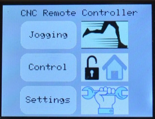


 The display initializes at
page zero. If a SD Card with the images correctly configured is inserted
the icons will be displayed.
The display initializes at
page zero. If a SD Card with the images correctly configured is inserted
the icons will be displayed.
Jogging (Page 1) - Move the X, Y or Z axes
Control (Page 2) - Send pre-defined GRBL commands to the machine
Settings (Page 3) - Adjust X Y movement speeds and spindle speed and
direction.
1. Jogging.
X Y and Z axes can be jogged in either direction using predefined distances, and the spindle can be turned on and off. A status screen is displayed briefly as each command is executed. Select the jog distance by tapping the corresponding yellow button. Jogging speed is set on the Settings page.
Use the right arrow to move to page 2.
2. Control.
Use the left arrow to go to page 1 or the right arrow to go to page 3.
3. Settings.
4. SD Card File list.
If a SD Card with files is inserted the files will be listed (maximum 7). The files are listed in the order they are stored in the root folder. Extensions are not considered and files with a name that begins with an underscore character ( '_' ) will be ignored.. The number of the current selected file is shown in a button at the bottom of the list (-1 means nothing is selected). Press the file number button to increment the selected file number. Press Start to send the selected file contents to the machine.
Use the left arrow to go to page 3 or the right arrow to go to page 5.
5. SD Card Command List.
This page is a duplicate of the previous page, except that the files listed are from the folder 'COMMAND' on the SD card, rather than the root folder. This page is designed for files of very short GCode programs, typically used to set the machine into a known state (eg, to set workspace zero without the need to jog the axes). It can also be used for GRBL commands not included elsewhere, such as $xx commands.
Use the left arrow to go to page 4 or the right arrow to go to page 6.
6. Status screen
Version details, TFT Display module details, available memory in the Mega, GRBL details.
Note: Available memory should not decrease while the controller is being used.
As of this document date the data memory usage is 49204 bytes (19%) of program storage space and 2817 bytes (34%) of dynamic memory.
The essential function of the controller is quite straightforward - collect input from the user, format it into the required GRBL text, and send it to the UART. But the number of available functions, and the settings that can be selected, are quite large, requiring a multi-page display, and the code for a multi-page touch screen can become quite complex. The main feature of the code below is that much of the processing is parameterised. In summary:
The result is that:
The scanning loops are exited as soon as the match is found.
* Buttons use a processing routine common to the button type, so for some pages more than one loop is used, depending on the update function required for the button. There are some cases where the processing is specific to the button and the processing for the type is skipped.Each movement command that is sent to the controller waits for a response. The response will be either 'ok' or 'error'. The response from the controller to the movement commands is typically received before the command has been fully executed - this is standard for GRBL. Therefore it is up to the operator to ensure that commands are not stacked up beyond the capacity of the controller buffer. This is about 16 commands plus 127 characters - it is unlikely to happen. Note that if the controller has not already been initialised from the PC connection then Unlock and Home may be requ9ired before any other commands are sent - this depends on GRBL configuration.
If an SD card is not inserted at boot time then the card functions are not available. The controller must be restarted to recognise an inserted card.
In order to display the logos the card must contain 3 files in the 'LOGO'
folder:
"LOGO/JOGGING.BMP"
"LOGO/COMMAND.BMP"
"LOGO/SETTINGS.BMP"
The files must be 100x60 in 24-bit colour format. File size should be 17.6KB.
For GCode files, only the first 7 files in the root folder will be displayed, regardless of their filename extensions. Filenames starting with an underscrore character are not displayed. There is no facility to select a file that is not listed. If you want to put other files on the card that that should not be listed then put them in a folder. Files should be formatted so that the lines end in LF only (if CRLF is used there may be multiple responses displayed).
Buttons are colour coded according to their function:
Movement command: CYAN. Axis Movement or On/Off command. Distance or
speed depends on settings
Movement setting: YELLOW Selects the setting for distance or speed
(rotating values - press again to cycle through the options).
Controller setting: ORANGE Sends a command to the controller
Select: GREY Selects a page or a filename.
Library Update
The button library that is part of the GFX graphics library needs to be adjusted in two ways.
1. The declarations for the 'label' argument in the 'initButton(...)'
functions have to be changed from 'char *' to 'const char *' in order to
avoid a warning that has been added into current versions of the Arduino
IDE compiler. This is at four places in Adafruit_GFX.h and the
corresponding four places in Adafruit_GFX.cpp. This change is optional, as
the warning can be ignored, but the warning may become an error in future
versions of the IDE. Updated versions of the library will likely remove
this warning.
2. A function to update the label needs to be added to the
Adafruit_GFX_Button class. The function template is added to
Adafruit_GFX.h and the function is added to Adafruit_GFX.cpp. This
function is required in order to avoid re-initialising the button when the
label changes - a process that is expensive in both processor cycles and
memory. This change has been proposed but not implemented in any version
available at this date (mid-2024).
Template (Adafruit_GFX.h):
Function (Adafruit_GFX.cpp):
The code can go immediately after the 'justReleased' method template and
function respectively. The changes have no effect on the use of the
library with existing applications. The change to update the button
label is required because the only existing method to do the update is to
re-initialise the label, which is wasteful of both memory and CPU cycles.
These changes do not affect the logic in any way and should be compatible with all existing uses of the library. Installing an update to the library will overwrite the changes, so it may be preferable to keep the modified copy in the sketch folder.
A note on the TFT-LCD displays.
1. The software was developed with a ILI9341 TFT display but any
'MCUFriend'-type display should work. Larger resolution displays
will work but the output does not adapt to the larger size. Smaller
resolution displays would be unusable. Some considerations for
different types of displays are:
- Touch screen calibration differences. Some varieties of compatible
display have significant differences in the values returned for touch and
must have their specific calibration values adjusted in the code.
- OpenSmart TFT shields may require changes in the library. The
details are in the MCUFriend library documentation.
2. There are a number of different types of these displays available from suppliers at very good prices. However, it appears that there is one type, at a better price than the others, that may be factory seconds because they all have the touch screen misaligned on the display. The reason is that the flexible strip attachment point for the touch screen is offset from the point where it attaches to the display. In order for the touch overlay to align correctly the strip needs a definite kink. It is possible to fix the problem by removing the touch overlay using gentle heat and a thin plastic blade, aligning it correctly, and re-attaching with the original glue and some additional glue along the edges to keep it aligned. The result is a perfectly aligned device at a remarkable price for a very functional colour display.
This page last updated 14/08/2024
