MISCELLANEOUS
1mm Ferrules.
Ferrules
are solid terminators for multi-strand wire. They are used where the wire
is connected to a screw or spring clamping terminal. The solid pin of the
ferrule provides a much better termination in the screw terminal than bare
wires.
 Note that
applying solder to the end of the wire in order to create a solid pin is
not recommended. The contact point with the connector is small and the
solder is liable to deform, especially if the connection is heated, and as
a result the wire loosens in the connector. Also, any bending or vibrating
force is concentrated at the point where the solder finishes, creating a
potential weak point. Ferrules overcome this problem.
Note that
applying solder to the end of the wire in order to create a solid pin is
not recommended. The contact point with the connector is small and the
solder is liable to deform, especially if the connection is heated, and as
a result the wire loosens in the connector. Also, any bending or vibrating
force is concentrated at the point where the solder finishes, creating a
potential weak point. Ferrules overcome this problem.
Ferrules also reduce the risk of a stray strand of wire escaping from the
screw terminal and shorting against an adjacent connector. When this
happens to a fine strand there is a risk of fire occurring before the fuse
blows.
Ferrules are typically crimped to the wire in order to ensure a solid
connection. A common form of ferrule is a tube which is crimped around the
wire to form the solid pin. However this does not work well for very small
ferrules.
A suggestion for very small ferrules is to use the pins from a male
solder-tail D-type connector, as commonly used for serial data
cables. The connector can be disassembled by folding out the tabs of the
shield and separating the molding pieces that secure the pins. The pins
then fall out.
The pins are exactly 1mm in diameter, and fit small screw and spring-contact
connectors very well. The soldered area is about 6mm long and provides a
solid connection for the wire. It is not subject to clamping pressure from
the connector so the soldered joint remains solid. The portion beyond
the connection pin can be covered with heatshrink, which helps to eliminate
a flexing point.
Header Supports.
When soldering multiple rows of headers to modules it is important to get
them properly aligned, or they will not fit the breadboard properly and
may break a solder joint when forced. In order to align rows
of headers correctly before soldering, insert several rows of pins across
the headers. These extra pins will ensure that the headers are
parallel and upright, and will also provide a convenient base for holding
the assembly during soldering.

CNC 3018 touch sensor block.
A precision 6mm block with wire connection for the height sensor input of
a 3018 CNC machine.
 The
economy versions of these machines come with a controller that supports
height sensing, but no sensor. The purpose of the sensor is to allow
the operator to define the zero level for the work surface. This can
be done by eye and feel, but a simple sensor that detects the circuit
between the tip of the milling bit and the sensor surface simplifies the
procedure considerably.
The
economy versions of these machines come with a controller that supports
height sensing, but no sensor. The purpose of the sensor is to allow
the operator to define the zero level for the work surface. This can
be done by eye and feel, but a simple sensor that detects the circuit
between the tip of the milling bit and the sensor surface simplifies the
procedure considerably.
The usual approach is to use a small piece of angle aluminium. The
problem is that the thickness is not precise, and it can be difficult to
get a reliable touch confirmation. The precision 6mm steel block
used here sits firmly on the work surface. It happens to have a
second hole through the middle which conceals that soldered connection
from the securing wire to the flexible connecting wire, and a piece of
heatshrink adds a little additional support to the solder joint. A 0.8mm
female header connects through to the controller board (there is a
matching wire running from the controller to the spindle).
Using a steel block has the added advantage that it can be stored against
a magnet that has been screwed or glued to the frame at a convenient
point.

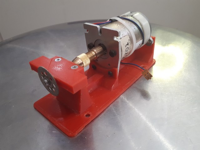
Proto-board Table Saw
 Many projects require pieces of prototyping board, either
for the actual prototyping or as the finished item, so cutting up pieces
of board is a common task. A cut-off disk on a Dremel tool does
this, but using it freehand is not always easy, and it's actually bigger
than is required. This little project re-purposed a small DC motor
(probably from a printer) by combining it with a collet, an arbor and a
cut-off disk in a 3D-printed mount to create a miniature table saw that
cuts straight edges through protoboard easily. It likely would find other
uses that projects require. The motor is an 18V 1.2A Tamagawa
TS3062N1 running at between 3,000 and 5,000 RPM. It is powered with
a laptop plugpack. The main shaft is plain and takes a collet. The rear
shaft is threaded, and in this case has been mounted with a grinding wheel
which can be used to clean up the edges of the cut. It is mounted using
the original mounting plate at the front: If this plate is missing the
printed base would need to be extended up to the holes adjacent to the
shaft, and the screws would have to be extended slightly to accomodate a
thicker support.
Many projects require pieces of prototyping board, either
for the actual prototyping or as the finished item, so cutting up pieces
of board is a common task. A cut-off disk on a Dremel tool does
this, but using it freehand is not always easy, and it's actually bigger
than is required. This little project re-purposed a small DC motor
(probably from a printer) by combining it with a collet, an arbor and a
cut-off disk in a 3D-printed mount to create a miniature table saw that
cuts straight edges through protoboard easily. It likely would find other
uses that projects require. The motor is an 18V 1.2A Tamagawa
TS3062N1 running at between 3,000 and 5,000 RPM. It is powered with
a laptop plugpack. The main shaft is plain and takes a collet. The rear
shaft is threaded, and in this case has been mounted with a grinding wheel
which can be used to clean up the edges of the cut. It is mounted using
the original mounting plate at the front: If this plate is missing the
printed base would need to be extended up to the holes adjacent to the
shaft, and the screws would have to be extended slightly to accomodate a
thicker support.
The arbor shaft is located in a pair of 8mm ball bearings. The ones
selected for this project had a lip on one side which enabled firm
mounting in the frame, but the screwed cap is actually firm enough to hold
plain bearings easily. The bearing cap could be extended to provide
a much larger table surface, but it has not been found necessary as
yet. If it was extended then supports would probably required from
the base. The screws for the bearing cap were specially selected for the
shallowness of the head, to enable a very shallow countersink.
The finished unit has a socket for the pluckpack mounted on the base, and
the motor wiring connected to the socket. An on-off switch could be
added. A reversing switch is also possible, to allow both left- and
right-handed use.
IDC Cable Clamping
Jig
 It is
possible to make up IDC cables without the need for a special clamping
tool. This jig is used to clamp the ribbon cable in the connector,
with both the cable and connector located in the jig so that the whole
assembly can be placed in a vice and clamped. The crosswise groove
accommodates the head of the connector, while the lengthwise groove
accommodates the cable. There are four inserts set into the jig so
that a clamp for the cable can be used, but this is often not
necessary. With the connector pushed into its slot, the cable laid
through the connector in the groove, and the cable clamp screwed down (if
required), the whole assembly is then positioned in the vice while being
held by the cable, and the vice tightened down. The completed unit
can be removed from the jig by pushing from the hole in the bottom.
The cable is then folded back over the header and the retaining bar pushed
on (this might also require pressure from the vice, at it is a very tight
fit).
It is
possible to make up IDC cables without the need for a special clamping
tool. This jig is used to clamp the ribbon cable in the connector,
with both the cable and connector located in the jig so that the whole
assembly can be placed in a vice and clamped. The crosswise groove
accommodates the head of the connector, while the lengthwise groove
accommodates the cable. There are four inserts set into the jig so
that a clamp for the cable can be used, but this is often not
necessary. With the connector pushed into its slot, the cable laid
through the connector in the groove, and the cable clamp screwed down (if
required), the whole assembly is then positioned in the vice while being
held by the cable, and the vice tightened down. The completed unit
can be removed from the jig by pushing from the hole in the bottom.
The cable is then folded back over the header and the retaining bar pushed
on (this might also require pressure from the vice, at it is a very tight
fit).
The obvious drawback of the device is that a different jig is required
for each size of connector, but they are easy to design and print, and
most projects use only one or two widths of cable.

Tip!
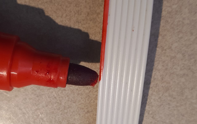
When multi-core ribbon cable is stripped down to the required number of
cores the red stripe marking pin one is lost. It can be
recovered using a broad-tipped permanent marker pen. With the pen
tip pushed gently vertically onto the edge of the cable and then run along
the length of the cable, a very neat edge marking can be achieved.
The width of the pen tip is sufficient to allow it to overlap slightly
around the edge of the ribbon cable, and produce a nice even line down
each side.
Male-Male Adapter

A 3-pin 90-degree header, with the centre pin removed, makes a simple
male-to-male 2-pin adapter that is sized correctly for the 5mm screw
connectors commonly used for power connections. A straight-pin header
would also work in the same way. The pin can usually be removed
using needle-nose pliers, but in some cases the header may require gentle
heating in order to remove the pin without risk of breaking the strip. The
plastic mounting strip can be pushed close into the 90-degree angle to
allow maximum length for both sides of the adapter.

Laser Shield Upgrade
 For those
who require spectacles for adequate close vision, using laser protective
eyeware can be a problem. This example shows how a cheap
plastic set of lenses from the $2 shop can be inserted at the back of the
protective eyeware in order to provide corrected vision when using
it. The plastic spectacles are best as the bridge can be drilled for
the bolt - metal-framed spectacles would require a small bracket to be
made up. The temple pieces are removed by undoing the screws, but they are
very tiny and it might be just as easy to cut through the plastic.
The only difficult part of the construction is drilling the actual shield
- the plastic needs to be well supported immediately behind the drill
point in order avoid strain on the shield while drilling and to minimize
any risk of cracking it. The lens frame is flexible enough to
be bent to the shape of the eyeware and the screw will hold it into shape,
but very gentle heat can be used to make it conform slightly better.
Clean the lens well before installing to avoid having to remove it later.
For those
who require spectacles for adequate close vision, using laser protective
eyeware can be a problem. This example shows how a cheap
plastic set of lenses from the $2 shop can be inserted at the back of the
protective eyeware in order to provide corrected vision when using
it. The plastic spectacles are best as the bridge can be drilled for
the bolt - metal-framed spectacles would require a small bracket to be
made up. The temple pieces are removed by undoing the screws, but they are
very tiny and it might be just as easy to cut through the plastic.
The only difficult part of the construction is drilling the actual shield
- the plastic needs to be well supported immediately behind the drill
point in order avoid strain on the shield while drilling and to minimize
any risk of cracking it. The lens frame is flexible enough to
be bent to the shape of the eyeware and the screw will hold it into shape,
but very gentle heat can be used to make it conform slightly better.
Clean the lens well before installing to avoid having to remove it later.
 Threaded
inserts are commonly used with 3D-printed parts. They are heated and
pushed into molded holes in the part to provide a secure holding for
screws which is much less prone to wear and slipping than plain threaded
plastic. The simplest way to both heat and place the insert is
with a soldering iron. The iron can be set to temperature
(about 225º C seems to be suitable for PLA). There are many
tutorials available showing the technique. But there are three
important points about the procedure that are often not mentioned in the
instructions.
Threaded
inserts are commonly used with 3D-printed parts. They are heated and
pushed into molded holes in the part to provide a secure holding for
screws which is much less prone to wear and slipping than plain threaded
plastic. The simplest way to both heat and place the insert is
with a soldering iron. The iron can be set to temperature
(about 225º C seems to be suitable for PLA). There are many
tutorials available showing the technique. But there are three
important points about the procedure that are often not mentioned in the
instructions.
1. A standard soldering iron tip can be used rather than a set of
insertion adapters, but in that case it should be ground down to the
insert diameter. By providing a tip that is the correct diameter
for the insert the insert will be heated thoroughly and evenly.
Turning the tip in a lathe is the best way to achieve this, but a copper
tip can be turned in a drill against a grinding stone if care is taken.
2. A definite shoulder should be left at the correct height along the
soldering iron tip for the insert. If the tip tapers and there is
not a definite shoulder then there is a risk that the insert will bind
with the tip and it will be pulled out of the part as the soldering iron
is withdrawn.
3. The insert should be the type that has a short length of shaft at the
blind end that can be used for alignment. The hole in the printed
part can then be made to the size of this alignment portion. Without
this feature it is very difficult to get the insert properly started in
the hole, and it will often twist off-centre as it is inserted.
On-line sellers often do not realize the importance of this small feature
and do not make it clear whether it exists or not. Always check the
images carefully when purchasing and return the item as faulty if it was
shown in the image but doesn't actually exist.

To assist with aligning the insert and getting it set flush with the
surface of the printed part, a nut can be set into the copper tip at the
shoulder point. This also assists in getting heat conducted into the
insert. This should be removable for those cases where it interferes with
surrounding material.
The correct temperature setting for the iron when inserting is usually
5°C to 10°C above the extruder temperature used for the material.
Note that the insert will distort surrounding material to some
extent. The inserting may not work correctly where the adjacent wall
thickness is not sufficient to absorb the distortion. Infill percentage
and wall thickness will affect the amount of distortion that can be
accommodated in a particular region.
The 4-port USB assembly fr om
a junked ATX motherboard can be mounted into a stand-alone case and
powered from a high-current 5V supply to provide a convenient recharging
station. The pins connected to the USB data lines are cut off short
and a small harness fabricated for connecting the four +5V pins and the
four Ground pins together. The supply connection can be to flying
leads, or if the bench power distribution has standardized DC connectors,
to the appropriate connectors.
om
a junked ATX motherboard can be mounted into a stand-alone case and
powered from a high-current 5V supply to provide a convenient recharging
station. The pins connected to the USB data lines are cut off short
and a small harness fabricated for connecting the four +5V pins and the
four Ground pins together. The supply connection can be to flying
leads, or if the bench power distribution has standardized DC connectors,
to the appropriate connectors.


 Stepper motors are configured as 3-, 4-, 5-, 6- or 8-wire. Three and
five wire steppers are designed for unipolar mode. Four wire steppers are
designed for bipolar mode, while six and eight wire steppers can be either
unipolar or bipolar.
Stepper motors are configured as 3-, 4-, 5-, 6- or 8-wire. Three and
five wire steppers are designed for unipolar mode. Four wire steppers are
designed for bipolar mode, while six and eight wire steppers can be either
unipolar or bipolar.
Unipolar is simpler to drive because a simple switching circuit can
change the polarity of the magnetic field by switching between the two
halves of the coils. For this reason it is very commonly used in small
consumer items, such as toys and small printers. Bipolar requires a
more complex driving circuit but creates better performance,especially if
microstepping is used, because the whole coil is energised when the
current direction is reversed.
Six wire and eight wire steppers are particularly useful because they
can be configured as either unipolar or bipolar. But many 5-wire
steppers can also be configured for either mode. This is because they are
actually constructed as 6-wire steppers with the centre taps connected
together at the wiring attachment point on a small PCB mounted externally
on the motor. If this is the arrangement, then cutting the trace
that connects the centre taps of the two coils means that the 5-wire
(unipolar) stepper is converted to 4-wire (bipolar).
In the first example the trace has been broken at the end of the PCB. The
stepper would be driven with a bipolar driver using orange/red and
brown/black - yellow is not used. The break has been scraped and tinned so
it can be easily bridged with a blob of solder if required for use with a
unipolar driver.
The popular 5V unipolar motor 28BYJ-48 can be converted using this
technique if the cover over the termination block is removed.
In the second example the arrow shows the place where the trace would be
broken to separate the centre taps of the two coils. In both examples
6 wires could be soldered to the PCB so that the selection between unipolar
and bipolar could be done at the other end of the wiring harness.
 Header
pins can be difficult to remove because each pin needs to be completely
desoldered. A heated plate or a heat gun will affect other components and
that may not be acceptable. However, it is possible to remove the
pins one by one if the plastic strip holding the pins is removed
first. Usually it can be lifted up and pulled of by first levering
the bottom edge with a sharp blade. If it is reluctant to move, a small
amount of heat will soften it very quickly. For long headers it may
be necessary to slice the plastic strip into several smaller
lengths. Once the plastic strip is removed the pins can be
unsoldered one by one and the holes cleaned out with a solder sucker
and/or wicking braid. In this example a straight header on the upper
surface had to be replaced with an angled header on the bottom surface in
order for the module to fit its case.
Header
pins can be difficult to remove because each pin needs to be completely
desoldered. A heated plate or a heat gun will affect other components and
that may not be acceptable. However, it is possible to remove the
pins one by one if the plastic strip holding the pins is removed
first. Usually it can be lifted up and pulled of by first levering
the bottom edge with a sharp blade. If it is reluctant to move, a small
amount of heat will soften it very quickly. For long headers it may
be necessary to slice the plastic strip into several smaller
lengths. Once the plastic strip is removed the pins can be
unsoldered one by one and the holes cleaned out with a solder sucker
and/or wicking braid. In this example a straight header on the upper
surface had to be replaced with an angled header on the bottom surface in
order for the module to fit its case.
The same technique can be used for double-row headers, but in that case
heating will almost certainly be required to soften the plastic before it
can be removed.


 Cheap import boards are often supplied with adjacent multi-pin components
misaligned. This is likely due to automatic placement and soldering
without using an alignment jig. In most cases this is not a problem, but
when the components are part of a module that needs to fit a case cutout,
or when some form of display is involved, the problem needs to be fixed.
If the modules can be aligned with a spring clamp of some form then it is
possible to heat the rear of the PCB with a heat gun to soften the solder
just enough to enable the modules to be move into alignment under the
pressure of the clamp. The images show two 4-digit 7-segment LED displays
clamped and then aligned.
Cheap import boards are often supplied with adjacent multi-pin components
misaligned. This is likely due to automatic placement and soldering
without using an alignment jig. In most cases this is not a problem, but
when the components are part of a module that needs to fit a case cutout,
or when some form of display is involved, the problem needs to be fixed.
If the modules can be aligned with a spring clamp of some form then it is
possible to heat the rear of the PCB with a heat gun to soften the solder
just enough to enable the modules to be move into alignment under the
pressure of the clamp. The images show two 4-digit 7-segment LED displays
clamped and then aligned.
The difficult part is judging the amount of heat to apply - some flux on
the solder joints will provide a guide, as it will bubble as the solder
melts.
The second image shows the before-and-after alignments.

Creating an image for CAD
alignment
 A
common task when using CAD to design enclosures for small projects is to map
the cutouts for a faceplate to the position of components such as switches
and LEDs already mounted on the PCB. To do this a photo of the PCB can
be used, but getting it exactly square to the camera can be difficult.
A solution is to scan it with a flatbed scanner, rather than photograph
it. Scanners are specifically designed to eliminate the distortion
usually associated with a camera lens at close range. The item can be
mounted on the scanner, with a small support if required, so it is exactly
square to the face. It would usually be scanned with the lid
raised. Note that an image manipulation program that allows precise
rotational alignment is useful if the item can't be aligned on the scanner
exactly - Paint.Net has an excellent add-in effect "Rotation Bilinear" that
can be used in conjunction with the rectangular selection tool to rotate the
image to perfect alignment. Other graphics applications likely have a
similar tool. The image can be loaded in the CAD application and
scaled using the largest and most identifiable features - usually the
perimeter of the PCB. Note that there may be one distortion
effect from the scanner, although it is easily allowed for: the light source
may not be exactly aligned with the sensor, so shadows of raised features
are not perfectly aligned with the top face of the feature. The
attached image shows how the shafts of the switches appear displaced towards
the bottom of the image by their shadow. The effect is easily allowed
for by using features that are not casting shadows. The example also shows
how cross-reference calculations between constraints can be used to align
components laid out in a pattern using the largest feature of the pattern.
In this case the distance between the components at the end of each row or
column is set and named. Then the intermediate distances are calculated as a
fraction of that distance (one of these must be reference only). The result
is that the component positions are automatically equally distributed along
the total length.
A
common task when using CAD to design enclosures for small projects is to map
the cutouts for a faceplate to the position of components such as switches
and LEDs already mounted on the PCB. To do this a photo of the PCB can
be used, but getting it exactly square to the camera can be difficult.
A solution is to scan it with a flatbed scanner, rather than photograph
it. Scanners are specifically designed to eliminate the distortion
usually associated with a camera lens at close range. The item can be
mounted on the scanner, with a small support if required, so it is exactly
square to the face. It would usually be scanned with the lid
raised. Note that an image manipulation program that allows precise
rotational alignment is useful if the item can't be aligned on the scanner
exactly - Paint.Net has an excellent add-in effect "Rotation Bilinear" that
can be used in conjunction with the rectangular selection tool to rotate the
image to perfect alignment. Other graphics applications likely have a
similar tool. The image can be loaded in the CAD application and
scaled using the largest and most identifiable features - usually the
perimeter of the PCB. Note that there may be one distortion
effect from the scanner, although it is easily allowed for: the light source
may not be exactly aligned with the sensor, so shadows of raised features
are not perfectly aligned with the top face of the feature. The
attached image shows how the shafts of the switches appear displaced towards
the bottom of the image by their shadow. The effect is easily allowed
for by using features that are not casting shadows. The example also shows
how cross-reference calculations between constraints can be used to align
components laid out in a pattern using the largest feature of the pattern.
In this case the distance between the components at the end of each row or
column is set and named. Then the intermediate distances are calculated as a
fraction of that distance (one of these must be reference only). The result
is that the component positions are automatically equally distributed along
the total length.
90-Degree Female
Headers

90-degree female headers don't actually exist, but it is easy to make
your own from a standard female header and a small section of
stripboard. This style of header can be useful where the required
height for a standard header is not available and it is not convenient to
either remove the pins and solder directly to the PCB, or replace the pins
with a 90-degree version.
Note that standard female headers have a significant excess length. It is
quite possible to carve away a few mm of the shroud of the header in order
to reduce the height required. If even more room is required the
male pins can be shortened slightly.
The example shows how to replace the jumpers used for setting for the
CW/CCW rotation of a DC motor driver with a 90-degree header wired to a
SPDT switch.
Zero-offset
risers
 There
are some cases where a shield that is normally inserted into a female
header strip on top of the MCU needs to be configured so that there is
zero offset between the base of the shield and the top of the headers on
the MCU in order to minimize the total height of the completed assembly.
The joystick/button shield on the UNO pictured here is an example.
At the same time, this shield will always be the topmost in any
stack, so there is no need for the long-tail female header usually used
for stackable shields. The alternative is to use simple pin headers,
but these are designed to be soldered from the top surface, with the
plastic spacer providing separation on the underside. This
results in a gap when the shield is inserted into the headers.
There
are some cases where a shield that is normally inserted into a female
header strip on top of the MCU needs to be configured so that there is
zero offset between the base of the shield and the top of the headers on
the MCU in order to minimize the total height of the completed assembly.
The joystick/button shield on the UNO pictured here is an example.
At the same time, this shield will always be the topmost in any
stack, so there is no need for the long-tail female header usually used
for stackable shields. The alternative is to use simple pin headers,
but these are designed to be soldered from the top surface, with the
plastic spacer providing separation on the underside. This
results in a gap when the shield is inserted into the headers.
The pins can be soldered in from the underside, but the protruding part
is then too short for good connection to the headers, and in any case the
solder joints create an unwanted gap.
The solution is to use the pins without the spacer and solder the pins
from the top The spacer is needed to correctly align the pins
while soldering, but once the pins are soldered into place the plastic
spacer is no longer needed. If it is removed after soldering then
the shield will sit down firmly on the headers of the MCU with no
additional gap. The image shows a joystick/button shield sitting
flush onto a UNO using this technique.
The important point is to ensure that all soldering is complete and
checked before removing the spacer! However it is also important to
get the correct positioning for the spacer before soldering it into place
on the underside - this ensures that the correct length of pin is
available for inserting into the female header. If the spacer is
left at its default position then, after removing it, there is too much
length to the pin and the shield will not sit flush with the
header. The image shows that the correct position for the
spacer is slightly more to the centre of the pins than the default - the
height of the pins above the PCB should be almost the same as the original
height of the pin above the spacer.
The spacer can be pushed up and down the pins to get the correct pin
height before soldering by inserting the whole row into a scrap of
stripboard and pressing against a solid surface. The spacer can be
easily removed when soldering is complete by gently heating with a heat
gun.
An alternative approach is to remove each pin from the strip and insert
it into place with the shield on top of the MCU, using the female header
of the MCU to position it correctly. This works, but it is difficult
to get right and requires much more time and trouble than using the spacer
for alignment and removing it afterwards. However soldering the pins from
the top while the shield is inserted in the MCU is a useful technique if
changes need to be made to individual pins after the strip is inserted.
Storage box for
crimper jaws

Terminal crimping tools are available in a multi-purpose format, where
the jaws are replaceable, being selected to suit the particular terminal
type to be crimped. Keeping track of the multiple jaws can be
difficult, especially when it comes to finding the matching second of a
pair. The fixture shown here simplifies that storage. It is a
rectangular block with slots that accommodate each pair of jaws, and locks
them in place with a skewer inserted through holes running across the
block.
Freecad Design
File
STL File

There are some modules, such as this type-C USB port, that are designed
to be soldered directly to a surface connector, like a SMD component. If
the configuration requires a wire to be attached instead, then it can be
difficult to make a connection that is not prone to flexing and
breakage. The image shows how a bifurcated socket insert can be
soldered to both sides of an edge connector on a PCB to provide a very
secure soldered joint.

Solderable Metallic
Strips

The metallic strips recovered from older-style flat ribbon cable
make very good connectors for certain types of solder connections.
They tin very easily, are flexible in one direction while being very stiff
in the other, are easy to handle while soldering and can be easily trimmed
to length with small snips. They are shown here used as
interconnects for LED modules. They are recovered by stripping back the
outer covering from the ribbon cable and then peeling the strips away from
the remaining substrate. If necessary they can be cleaned by pulling
through between a razor blade and a flat surface. They are useful in cases
where lengths are too short to be manageable with multi-strand wire, and
where single strand that is thick enough to be handled is too stiff.
USB Type C Socket Mounting
 There
are USB Type C socket modules available that are designed for pins or
soldered connections, but have no mounting points. If they aren't
pinned or soldered direct to a custom PCB, then they can be soldered to one
end of a common style of prototyping board. The type with a 4x0.1"
edge connector has two mounting holes at each end with space between that
exactly fits the width of the socket module. The result is a USB socket that
can be mounted very firmly in the case.
There
are USB Type C socket modules available that are designed for pins or
soldered connections, but have no mounting points. If they aren't
pinned or soldered direct to a custom PCB, then they can be soldered to one
end of a common style of prototyping board. The type with a 4x0.1"
edge connector has two mounting holes at each end with space between that
exactly fits the width of the socket module. The result is a USB socket that
can be mounted very firmly in the case.
This page last updated 31st October 2024
