
There is a variety of small DC motors that include an AC tachometer output. These motors are typically in the 12-18V range, and spin at speeds of up to 2800RPM. They include a tachometer as part of the motor. The AC tachometer produces a sine wave (AC) output with a signal level that is proportional to the motor speed, enabling the motor to be used in a closed-loop configuration. The motors can be identified by a second pair of wires, often attached at the opposite end to the drive wires, and sometimes associated with an distinct end cap.
Because of the way that the output is created, the speed of rotation is indicated by both amplitude and frequency. The amplitude is useful for a simple analog display, but frequency is much more useful for processing in a MCU, for instance in a closed-loop control configuration.
This simple circuit converts the sine wave output into a digital signal that can be used with a MCU to measure the speed of the motor without the need for ADC. This measurement is more accurate than using the signal amplitude, although account must be taken of the number of of the number of pulsess per revolution, which can vary for different motors.

 The
tachometer output is an isolated AC signal that has a voltage that depends
on the type of motor and the motor speed, and can vary over a wide range.
In order to ensure that the current flow is controlled the signal is
isolated. One side is fed to a low-value capacitor, while the other is
tied to ground. A Zener diode is connected between the output of the
capacitor and ground. This does two things. Firstly it provides
half-wave rectification, so the sine wave output of the tachometer is
changed to a pulsed positive signal. Secondly it limits the positive
excursion of the signal to the 4.2V value of the Zener. This occurs
because the Zener conducts when the voltage across it exceeds that value.
Because of the capacitor isolation the current through the Zener is very
small - typically about 2mA, and less that 5mA even for large
motors. A 1/4W Zener is suitable in almost all cases.
The
tachometer output is an isolated AC signal that has a voltage that depends
on the type of motor and the motor speed, and can vary over a wide range.
In order to ensure that the current flow is controlled the signal is
isolated. One side is fed to a low-value capacitor, while the other is
tied to ground. A Zener diode is connected between the output of the
capacitor and ground. This does two things. Firstly it provides
half-wave rectification, so the sine wave output of the tachometer is
changed to a pulsed positive signal. Secondly it limits the positive
excursion of the signal to the 4.2V value of the Zener. This occurs
because the Zener conducts when the voltage across it exceeds that value.
Because of the capacitor isolation the current through the Zener is very
small - typically about 2mA, and less that 5mA even for large
motors. A 1/4W Zener is suitable in almost all cases.

The output of the tachometer is a TTL digital signal derived from the sine wave input of the AC generator. It runs at some multiple of the motor RPM, depending on the number of poles in the AC generator.
The calibration that is required is to determine the number of poles in the AC generator portion of the DC motor. This number determines how many pulses per revolution are generated. This factor needs to be applied to the raw pulse count to calculate the RPM.
If the motor specifications are known, or if the motor can be disassembled and examined, then this step is not required.
This calibration does not include any adjustment for timing errors in the measuring device (eg, the MCU). If that adjustment is required it must be done separately.
The arrangement to find the number of poles requires the following equipment:
The calibration procedure is to attach the strobe wheel to the motor, then connect the variable speed driver. Also connect the driver PWM to the logic analyzer.
Connect the tachometer to the motor and also to the logic analyzer, set to display the pulse frequency speed in kHz.
Ensure that the grounds for all the devices are connected together. The tachometer output is usually isolated so either connection can be used as ground.
The jitter at the high level of the buffer output is apparently caused by interference from the motor controller and is specific to this hardware arrangement. It does not affect the result.
 The
PWM controller is set to a duty cycle of 1% - the briefest possible pulse
per cycle. This ensures a very brief LED flash, so that the rotation of
the strobe wheel is captured. The output of the controller is
connected through the MOSFET driver to the LED array. The LED array
is shone onto the strobe wheel, and the frequency of the PWM controller is
adjusted until the strobe wheel image is stationery. The number of
poles is then calculated as the motor frequency divided by the strobe
frequency.
The
PWM controller is set to a duty cycle of 1% - the briefest possible pulse
per cycle. This ensures a very brief LED flash, so that the rotation of
the strobe wheel is captured. The output of the controller is
connected through the MOSFET driver to the LED array. The LED array
is shone onto the strobe wheel, and the frequency of the PWM controller is
adjusted until the strobe wheel image is stationery. The number of
poles is then calculated as the motor frequency divided by the strobe
frequency.
For instance, if the tachometer is recording a frequency of 800Hz and the strobe frequency at which the strobe wheel is frozen is 100Hz then the AC generator has 8 poles.
Note that a strobe wheel that is symmetrical will appear nearly stationery at integer fractions and integer multiples of the motor speed. However, some level of symmetry is useful in finding the speed at which there is a match. The suggested layout of the wheel is partly symmetrical, but enables the multiple to be identified. The speed match is exact when there are no 'ghost' images of the red line.
The strobe pulse from the PWM controller is fed to the logic analyzer - this signal may require a buffer, in which case a spare input/output on the LS7414 is suitable. The Tachometer output is fed to another channel on the logic analyzer, so the two frequencies can be compared.
Note that the measured frequency in this case is the frequency of the cycle. This is because the timing calculation for the logic analyzer is set to trigger on either the leading or trailing edge of the cycle, not both. This means the frequency can be directly converted to revolutions. If the analyzer triggers on both rising and falling edges, or if the two traces are configured to trigger differently, this must be allowed for in the frequency comparison. Both traces triggering on one edge only is by far the simplest arrangement.

The strobe wheel can be any suitable pattern, but the example shown here works well. It is symmetrical except for one red spoke. The pattern makes it easy to determine when the speed is synchronized to the strobe LED, but the single red spoke shows clearly when the synchronization is other than one-to-one. The second example shows half flash speed - the red spoke is at the top on every second revolution. The third example shows double flash speed - the red spoke is revealed at each full revolution and also at each half revolution. Similar patterns reveal other integer multiples and fractions.
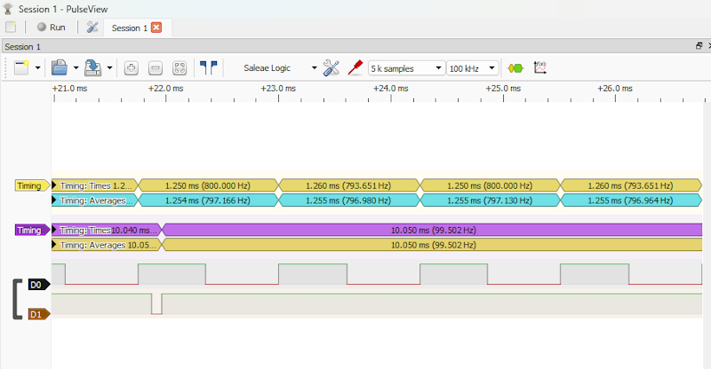
The display from the logic analyzer shows the result when the strobe light shows the wheel as stationery. Channel 0 is the tachometer, Channel 1 is the strobe trigger.
Channel 1 is firing at a rate of ~100Hz. The tachometer is pulsing at a rate of ~800Hz. Because the strobe wheel is stationery at those settings, there must be 1 strobe pulse for every rotation of the strobe wheel.
So when the tachometer is connected to the MCU the frequency reading from the tachometer must be divided by 8 to get the motor revolutions per second. In practice, it is sometimes the case that the actual motor rate is not required, and the tachometer rate can be used without adjustment. But when the rate is required, the adjustment must be made.
