NRF24L01 Transceiver Example
A wireless transmitter/receiver using the NRF24L01 wireless module and a
soil moisture sensor. This project is still in prototyping stage,
pending development of a suitable battery module.
This project is a simple example of remote monitoring using a pair of
wireless transceivers to transmit the data from the remote monitoring
point to the display/recording point. It uses the transceivers in
one-way communication only - this is appropriate for the type of
monitoring being undertaken but two-way communication could easily be
added.
Arduino Nanos have been used as the MCU because they are small and
inexpensive, and the processing load is very small. Any similar MCU could
be used. The transmitting device requires an analog input for the
sensor, while the receiving device requires an I2C output for the display.
Both units must support ISP for the wireless units. The sample code
includes a procedure for putting the transmitting end MCU into sleep mode,
so a MCU that supports sleep can take advantage of that.
The NRF24L01 transceivers are 3.3V devices but in this example they are
used with adapters that permit operation at 5v. This simplifies the
installation and also offloads the 3.3V supply from the Nano - a useful
function, as the power requirement of the transceiver can be quite high if
operated in the high-power mode. Note that the transceiver inputs
and outputs are 5v tolerant, so if the adapter is not used it is only the
supply of power that needs to be considered.
Parts:
Arduino
Nano x 2
NRF24L01 transceiver module x 2
NRF24L01 power adapter x 2 (recommended)
1602A/I2C LCD display with I2C interface (or
similar)
Soil Moisture Sensor
Battery 5V
Breadboards and dupont connectors (for prototype)
Schematic
 The
Nano ISP interface, together with the 5v and ground power and the two
control lines are wired through to the transceiver adapter. The adapter
plugs directly into the transceiver module. For the transmitter the soil
moisture sensor is wired to A0 at the Arduino. For the
receiver, the LCD display is wired to the I2C pins of the Arduino.
The
Nano ISP interface, together with the 5v and ground power and the two
control lines are wired through to the transceiver adapter. The adapter
plugs directly into the transceiver module. For the transmitter the soil
moisture sensor is wired to A0 at the Arduino. For the
receiver, the LCD display is wired to the I2C pins of the Arduino.
Note that the adapter has three sets of connectors - two headers and one
socket. The pin numbering in the diagram refers to the connectors, so
there are duplicate numbers.
The schematic indicates a battery for the 5V supply: for the transmitter
this is a battery module based on a 16850 LiPo battery with a
charger/regulator, while for the receiver it is a USB plugpack.
.
Assembly
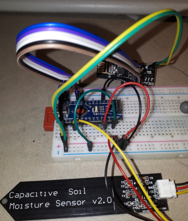
The parts are assembled on a pair of prototyping boards.
Prototyping is important for this application as debugging can be
difficult when both devices have to be operating properly in order to see
any action at all.
The NRF24L01 can draw quite a lot of current in transmit mode, so it is
essential that the +5V supply and the ground leads make a good connection.
The final construction simply consists of tying the leads from the
various modules together, so it could be done without a prototyping board,
once the positions and fitting in a custom case was established.
Alternatively, all the modules could be fitted to a large prototyping
board and the mounting pins wired together to make the connections.
The battery and sensor parts of the transmitter need special
consideration for sealing. The battery will need an opening for the
charger, but if a battery of sufficient capacity is available then
charging will be sufficiently infrequent to allow for a screwed cover. The
sensor requires a cover for the cable and components - they should be
potted in gel or hot glue to ensure complete waterproofing.
The radio modules used in this example are a mix of the small modules,
with an antenna etched on the PCB, and the larger module, with a large
screw-on antenna. The arrangement that works best is a matter of
experiment, and depends very much on location and distance.
Multiple channels and two bandwidths are selectable, as well as multiple
power levels for the transmitter, so the number of possible combinations
is very large.

Code
The code is nearly identical for both pieces. For the NRF24L01
code, there are two small changes to identify the transmitter and
receiver. For the sensor the only code required is to set up the A0 pin as
input, and then to read the value and format it for sending. For the
display it is a little more complex - the LCD library must be included,
and the device initialized. When data is received it is printed to
the display.
Transmitter (Sensor) Code
Receiver (Display) Code
This page last updated 18 August 2024
