Triple Driver
A driver for a 3-colour LED strip (5050), or for 3 single-line LED strips
(WS2812) or for multiple DC motors.
This project is a copy of commercial products that are available for the
same purpose, but it incorporates a much larger heatsink and a fan,
allowing considerably higher-current loads to be driver. It also
incorporates back-EMF protection diodes. The FET can handle a theoretical
maximum of 100V at 5A, but the regulator for the fan is limited to 45V
maximum. The practical limit is dependent on the construction method
and the ventilation allowed for the enclosure, but 3A should be achievable
without undue stress on components.
The driver is a 'low-side switch'. That is, the device controls the
power to the output by switching the negative side of the load (LEDs,
motor, etc) to ground. The positive supply to the load is wired
straight through and plays no part in the switchinig,
Parts:
3 x IRF520 N-Channel MOSFET. Similar varieties of MOSFET would work as
well.*
Heatsink to match, with mounting hardware (insulated)
6 x screw terminal panel (3x VDD/Gnd for Load)
2 x screw terminal panel (VDD/Gnd for Load Supply)
4 x male headers or equivalent (for 3x control signals + Gnd)
3 x 1N4004 diodes or similar (1N5406 in this example)
Prototyping board and hookup wire
* The IRF520 was used here because it is cheap and available and adequate
for the intended use. However it is not the best choice for use with
the 5V logic of an Arduino. A better choice would be IRLZ44,
IRL540 or any MOSFET with "RDS(on)" of 5V. These are described as 'Logic
level", meaning TTL level logic.
For fan:
7812 12V linear regulator TO220
SPDT switch (12V, 1A minimum)
Fan 12V
Schematic
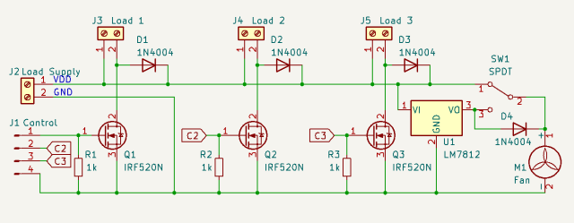
External connections fall into three parts:
J1 Control is the three TTL-level inputs, plus earth, that provide the
PWM signal to drive the outputs.
J2 Load Supply is the high-current supply for the devices to be
driven. This can be up to about 45V (limited by the fan regulator).
J3, J4, J5 are the load outputs. Each output includes the V+ rail
from the Load Supply (positive terminal of load), and the switched output
(negative terminal of load).
The control inputs are held low by resistors R1 through R3. When an input
is taken high the FET Q1, Q2 or Q3 is switched on and takes the
corresponding load output to ground, completing the circuit from the load
V+ through the load to Ground (a low-side switch). Diodes D1, D2 and
D3 will direct any back EMF back to the motor, thereby protecting the FET
from potentially excessive voltage spikes.
U1 is a 7812 linear voltage regulator providing a regulated 12V to the
fan. Switch SW1 is provided so that the regulator can be bypassed
when the Load Supply voltage is less that about 14V, as the regulator will
not regulate below that voltage, and the fan can be driven directly.
Note: The IRF520N in TO-220 format has the Drain
terminal connected to the tab. If a single heatsink is used (as in
this project) then the FETs must be insulated from the heatsink. If
multiple heatsinks are used then the there is no need to insulate the FETs
if the heatsinks are carefully separated from each other and from any of
the other components or wiring. The insulating hardware includes a
non-conductive pad and a screw sleeve. Heatsink compound should be
used between the pad and the heatsink and the pad and the FET.
Assembled
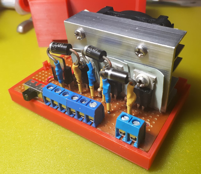 The
parts are assembled on a piece of prototying board. The Load Supply
and the Load terminals are arranged along one side, along with the switch
for the fan. Note the insulating material for the FETs. The
heatsink is supported by the FETs. The wiring on the underside uses a
combination of board traces, solid copper wire to connect traces, and
insulated stranded wire for longer interconnects. The protecting
diodes are mounted by soldering to female headers pushed onto pins solder
through from the underside.
The
parts are assembled on a piece of prototying board. The Load Supply
and the Load terminals are arranged along one side, along with the switch
for the fan. Note the insulating material for the FETs. The
heatsink is supported by the FETs. The wiring on the underside uses a
combination of board traces, solid copper wire to connect traces, and
insulated stranded wire for longer interconnects. The protecting
diodes are mounted by soldering to female headers pushed onto pins solder
through from the underside.
.
Usage
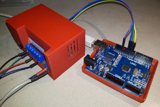 Packaged
in a case, with a UNO for controller. Front connections are the 12V
+/- power supply and the RGB+Ground leads for a LED strip. The
Arduino pins (9, 10, 11 and Gnd) are connected to the screw
terminals at the back. The case has vents at the back and sides. In
this configuration it easily powered a 5M strip of 5050 three-colour LEDs.
Packaged
in a case, with a UNO for controller. Front connections are the 12V
+/- power supply and the RGB+Ground leads for a LED strip. The
Arduino pins (9, 10, 11 and Gnd) are connected to the screw
terminals at the back. The case has vents at the back and sides. In
this configuration it easily powered a 5M strip of 5050 three-colour LEDs.
This page last updated 12 December 2022
