ESP01 Serial Adapter Modification
Modifying the ESP01 Serial Adapter board to use as a programmer.
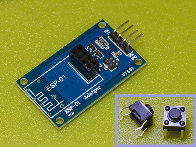
A simple serial adapter board for the ESP01 is available on ALI and other
places. It consists of a 2x4 female header on a PCB that includes an
AMS1117 3.3V regulator, two transistors (J1?) as level converters, a
few resistors and a bypass capacitor. There are male headers to
connect to the serial port and provide 5V and Gnd to make the serial port
compatible with the UART. Using this adapter it is possible to
connect the ESP01 serial port with a PC (or similar) serial port for
duplex communication. This adapter is ideal for use with the CNC
controller wireless link.
To make the adapter usable for programming two switches must be added.
They are both miniature single-pole NO momentary 4-pin switches.
One will be a reset switch - when programming through a serial port
without control signals the ESP will not be automatically reset at the
completion of the download, so this switch will be used to do the
reset. The other switch is used to connect GPIO0 to ground in order
to put the module into programming mode. This can be used in conjunction
with the reset switch to avoid having to power-cycle the module after
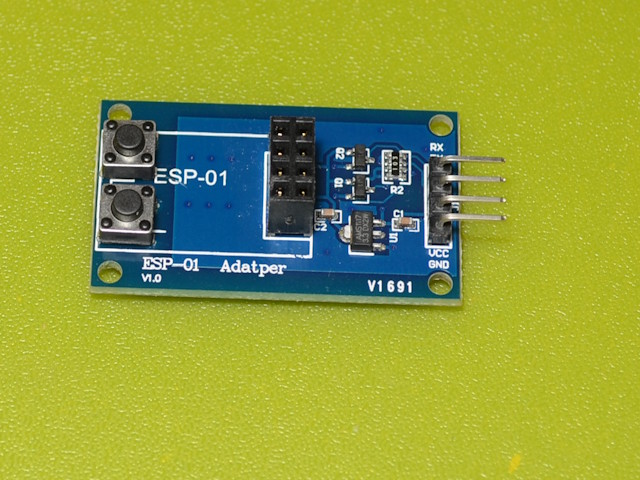
programming. There is room for the two switches at the end of the
module opposite the header: there is no PCB circuitry in this area.
 The
first image shows the four 1mm holes drilled for the two switches.
Note that although these switches have four legs, they are single pole - the
legs on each side are common. Note also that the ground plane for the
PCB ends well clear of the through-holes, although there would be no problem
if it was to be drilled through. The switches are orientated
with their shorter edge parallel with the top of the board - this means that
the four legs required for connection are the ones nearest the adapter
header. There are similar switches available with two legs - they will
function exactly the same way, but will not provide quite as secure a
mounting.
 When
the switches are pushed into the holes the legs can be bent slightly to make
them a tight fit. A drop of glue could also be used under each switch,
but in practice the bend in the legs and the soldering that will be done on
the underside is sufficient to hold them quite firmly.
 The
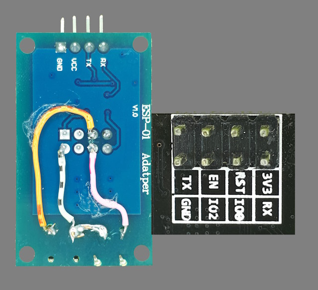
two centre legs can be connected together as a common ground. The
outer leg of one switch is connected to GPIO0 and the the outer leg of the
second switch is connected to RST. A small dab of glue can be used
to hold the wiring to the surface of the PCB.
I haven't provided numbering for the pins to solder because there does
not seem to be agreement on how the header pins should be
numbered! Use a ESP01 pinout diagram, carefully oriented with
the pins uppermost, to identify Gnd, GPIO0 and RST.

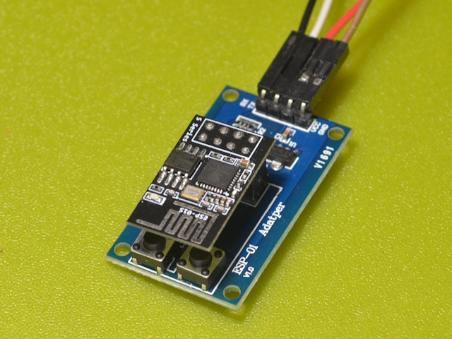
To use the adapter, connect VCC and GND to the header pins from the power
supply, and connect the Tx and Rx header pins to the corresponding pins on
the RS232-TTL adapter. Fire up the Arduino IDE and select the COMx
port (probably COM1 - most PCs nowadays don't have more than one COM
port). Plug an ESP01 into the adapter header. Press and hold
the GPIO0 switch and briefly press the RST switch to put the ESP01 into
programming mode. Upload the sketch. When the upload is completed,
press the RST switch. The ESP is now running the sketch.
Note: Arduino IDE version 1.x works just fine with any PC I
have tested, but some PCs will not work with Arduino IDE 2.x. The
reason is that some PC serial ports cannot select the particular baud rate
that the Arduino IDE 2.x uses during program upload. It appears that
the USB serial Port Driver used with USB-to-Serial adapters has more
flexibility in baud rates than the PC hardware. There is no easy way
around this, so if you see an error message about failing to set the baud
rate, use a 1.x version of the IDE.
This page last updated 1 February 2025 
 The
two centre legs can be connected together as a common ground. The
outer leg of one switch is connected to GPIO0 and the the outer leg of the
second switch is connected to RST. A small dab of glue can be used
to hold the wiring to the surface of the PCB.
 The
first image shows the four 1mm holes drilled for the two switches.
Note that although these switches have four legs, they are single pole - the
legs on each side are common. Note also that the ground plane for the
PCB ends well clear of the through-holes, although there would be no problem
if it was to be drilled through. The switches are orientated
with their shorter edge parallel with the top of the board - this means that
the four legs required for connection are the ones nearest the adapter
header. There are similar switches available with two legs - they will
function exactly the same way, but will not provide quite as secure a
mounting.
 When
the switches are pushed into the holes the legs can be bent slightly to make
them a tight fit. A drop of glue could also be used under each switch,
but in practice the bend in the legs and the soldering that will be done on
the underside is sufficient to hold them quite firmly.

