Power Bank
A power bank based on a single 18650 cell, used to provide a portable 5v
battery charger.
This project is mostly designing and printing the case - there is no
custom circuitry involved, other than the battery connection.
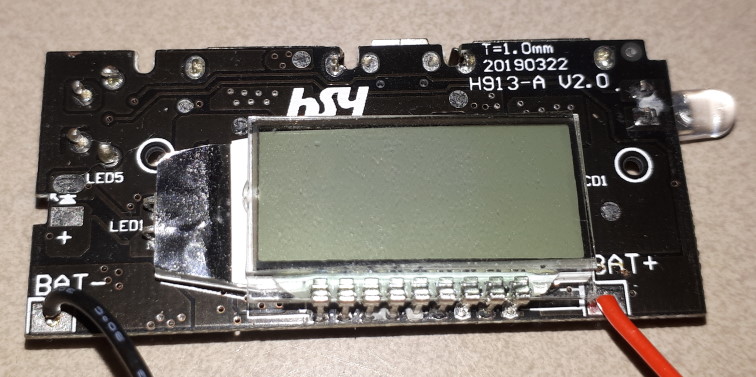
The charge controller is a generic controller providing 5v at 2.1A and 5v
at 1A. There may be variations of the type - the particular one used here
measures 28.5mm x 13mm and has a LED extending from one side at the front,
and a momentary push switch at the other side. It also has an
additional solder point marked 'LED5', but the usage is unknown.
 The
module is designed to use any 3.7v Lithium-Ion battery as a power
store. It has one type-C USB port through which the battery can be
charged, and two USB type-A ports for supplying power to a device.
Note: This device is a power bank - it only delivers power when the
attached device needs to be charged. When it detects that charging
is complete it removes power to the device. It therefore is
probably not suitable as a general purpose 5v supply - if the load is
insufficient then it will not turn on, and if the load disappears it turns
off and does not turn on again until disconnected and reconnected.
It could be used a general purpose 5v supply if the device it is powering
continues to draw a significant current.
Note that the battery can be used with multiple cells (in parallel, so
the voltage is 3.7v) but there is no cell balancing mechanism in the
module.
The case
 A
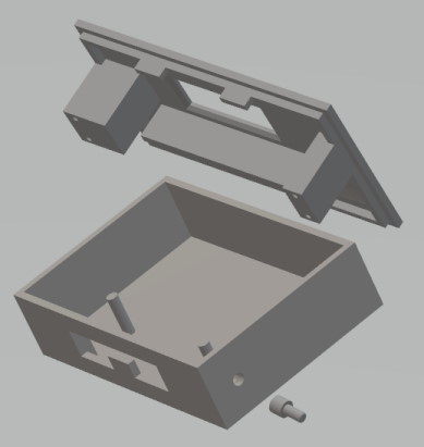
case for the module turns out to be rather complicated. The module
does not have provision for good support in a case. There are two
holes in the PCB, but only one of them is really accessible, with a decent
area for support on the rear. The case included support posts under
the mounting holes, but the module was not screwed to the posts.
Instead, the module is fixed between two sturdy pillars which also serve
to position the lid of the case off the base. In addition there is a
shelf at the ends of the front part of the PCB, where there is a blank
area on the underside.
The pillars supporting the lid were provided with holes to enable
screwing through from the base, but they were not used.
The Layout
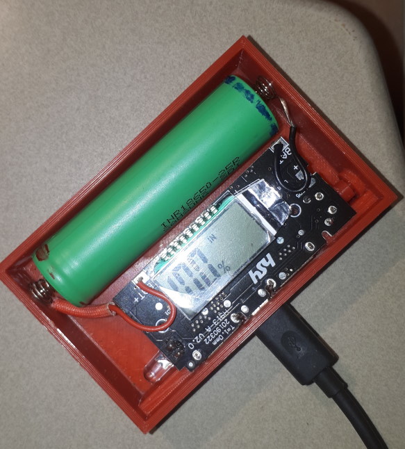
 The
case was designed with very tight tolerances so that the module was held
firmly and the lid fitted tightly: some fettling was required to get
everything in. The battery is held in position by a matching groove
in the lid, but is is also separated from the module by the shelf that
holds the module against the front face.
The back of the cutour for the display was chamfered to ensure the
display fitted as close to the top surface of the lid as possible - this
is particularly important for the rear edge of the display where the
solder points are located.
The module has a momentary push switch under the PCB at the front.
The case was built with a hole and bezel in front of the switch, and a
push button was made which enables the switch to be activated from outside
the case.
Coiled spiral springs were used for the battery connection. This
provides a tight fit while still allowing for easy replacement of the
battery in the future.
To assemble, the module is positioned in the lid between the pillars,
hard up against the top face. The lid assembly is lowered onto the
base at the front. When the USB ports are correctly positioned
against the front cutouts, the rear of the lid can be snapped into
position.
There is a power indicator LED at the end of the PCB. No provision
was made in the case for this, as the LED shows through the case without a
problem. If the case is printed with a less translucent filament
then it would be possible to drill a small hole in the lid at the position
of the LED, fill it with hot glue and cut it off flush, so that the LED
shines through.
Usage
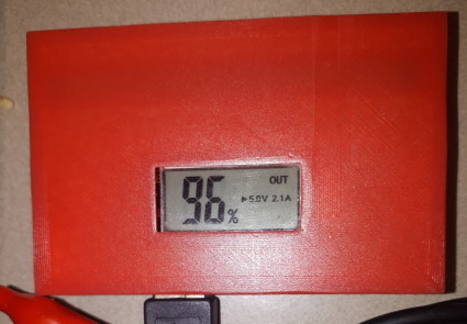
 When
power is supplied to the module through the centre ('C') connector the
display shows "IN" and the percentage charge of the battery.
When a device is plugged into either 'A' connector the display shows 'OUT'
and also indicates the current battery charge and which port is in
use. The left-hand port is identified as '5.0V 2.1A' while the
right-hand port is identified as "5.0V 1A". The push button at the
side can be used to turn the module off when there is a load attached, or
to turn it back on. When the module turns on the display is illuminated
for about 30s: a short press on the button will also illuminate the
display.
When
power is supplied to the module through the centre ('C') connector the
display shows "IN" and the percentage charge of the battery.
When a device is plugged into either 'A' connector the display shows 'OUT'
and also indicates the current battery charge and which port is in
use. The left-hand port is identified as '5.0V 2.1A' while the
right-hand port is identified as "5.0V 1A". The push button at the
side can be used to turn the module off when there is a load attached, or
to turn it back on. When the module turns on the display is illuminated
for about 30s: a short press on the button will also illuminate the
display.
This page last updated 19 August 2024.

 The
module is designed to use any 3.7v Lithium-Ion battery as a power
store. It has one type-C USB port through which the battery can be
charged, and two USB type-A ports for supplying power to a device.
Note: This device is a power bank - it only delivers power when the
attached device needs to be charged. When it detects that charging
is complete it removes power to the device. It therefore is
probably not suitable as a general purpose 5v supply - if the load is
insufficient then it will not turn on, and if the load disappears it turns
off and does not turn on again until disconnected and reconnected.
 A
case for the module turns out to be rather complicated. The module
does not have provision for good support in a case. There are two
holes in the PCB, but only one of them is really accessible, with a decent
area for support on the rear. The case included support posts under
the mounting holes, but the module was not screwed to the posts.
Instead, the module is fixed between two sturdy pillars which also serve
to position the lid of the case off the base. In addition there is a
shelf at the ends of the front part of the PCB, where there is a blank
area on the underside.
  The
case was designed with very tight tolerances so that the module was held
firmly and the lid fitted tightly: some fettling was required to get
everything in. The battery is held in position by a matching groove
in the lid, but is is also separated from the module by the shelf that
holds the module against the front face.
 When
power is supplied to the module through the centre ('C') connector the
display shows "IN" and the percentage charge of the battery.
When a device is plugged into either 'A' connector the display shows 'OUT'
and also indicates the current battery charge and which port is in
use. The left-hand port is identified as '5.0V 2.1A' while the
right-hand port is identified as "5.0V 1A". The push button at the
side can be used to turn the module off when there is a load attached, or
to turn it back on. When the module turns on the display is illuminated
for about 30s: a short press on the button will also illuminate the
display.
When
power is supplied to the module through the centre ('C') connector the
display shows "IN" and the percentage charge of the battery.
When a device is plugged into either 'A' connector the display shows 'OUT'
and also indicates the current battery charge and which port is in
use. The left-hand port is identified as '5.0V 2.1A' while the
right-hand port is identified as "5.0V 1A". The push button at the
side can be used to turn the module off when there is a load attached, or
to turn it back on. When the module turns on the display is illuminated
for about 30s: a short press on the button will also illuminate the
display.