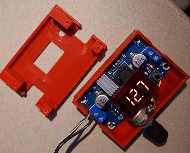
This project involves designing and printing a case for a commercial DC Voltage Power Regulator module. The module is modified slightly to make it suitable for mounting in a case.
Note: This design refers to the style of regulator that includes a
3-digit LED display and a adjustable potentiometer. There are
similar devices that do not include the display. and have a different mode
of operation.
The potentiometer size is controlled by the space available in the case.
For this project it was just over 16mm in diameter and 10mm depth below
the mounting face. The terminals protrude at one side and there is a
locating lug on the front face. This size potentiometer resulted in a case
with the following characteristics :
PCB Standoff from the base is 7.40mm, to give a PCB top surface at 9mm
(1.6mm PCB thickness).
Base internal wall height is 14mm. This allows for the potentiometer shaft
hole to be entirely within the wall of the base.
Base internal width is 46mm. This is 36mm for the PCB and 10mm for the
potentiometer. (length is 66mm - a neat fit for the PCB)
Walls and floor are 2mm, although this does not affect the installation of
the components.
Lid interior wall height is 4mm. This puts the inside surface of the top
of the lid right on top of the highest part of the PCB (the input and
output capacitors).
The top of the 3mm acrylic, when sitting on top of the display, is then
flush with the inside surface of the lid.
The distance from the top of the mode switch to the inside surface of the lid is therefore 6.8mm - this sets the dimension for the shoulder of the switch button shaft.
The trimpot is removed from the PCB - a heat gun is the simplest way to do this but a soldering iron and solder sucker or wick will also work. Clean out the solder holes and attach about 6cm insulated hookup wire.. The connection can be made from the bottom side of the board, so that the wire can be run under the PCB and any excess tucked away. Solder the other ends to the potentiometer following the same pattern as the PCB holes. Note the if the potentiometer has a locating pin on the face a hole for the pin must be allowed in the front of the base.
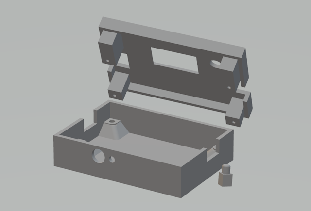
The PCB sits on standoffs molded into the base of the case. Countersunk screw holes are let into the base.
The acrylic is cut larger than the surface of the LED display. Thin strips of transparent double-sided tape are then applied along the top and bottom edges, and the acrylic stuck to the display so that the adhesive strip just overlaps onto the top and bottom of the display.
The heatsink is glued to the regulator with thermal adhesive or a thermal pad. If high-current operation is likely then it would be worthwhile to provide ventilation holes in the case.
The lid is molded with an aligning piece at each corner which incorporate holes for the screws that are inserted through the base, sandwiching the PCB between the two parts.
The switch is operated using a shaft inserted between the lid and the switch. The shaft is positioned on the switch using a cutout in the base, and a shoulder near the top prevents it from coming out. A cap can be made for the top of the shaft, but in this case it has simply been rounded and smoothed. An alternative to a shaft is to mount a small momentary switch on the face of the lid and wire it to the PCB switch. In this case there is no need to remove the existing switch.
No attempt has been made to make the indicator LEDs available at the face, as operation of the device indicates this isn't needed. It would be possible, however, to attach a pair of thin clear plastic rods to holes in the top face to 'pipe' the light from the LEDs.