LiPo Battery Charger Case
This is a small project that simply puts a small LiPo battery charger
module in a case. The charger is used to recharge LiPo batteries
recovered from discarded equipment which are used for powering USB audio
receivers connected to powered speakers at various locations.
However, it involves a mounting method that is suitable for similar
modules that use PC boards that do not provide suitable mounting points,
but which require a secure mounting because they support a USB connector,
which may require some force for insertion and removal of the USB
connector.
Module

The charger module consists of the USB connector and the components
mounted on a 26mm x 17mm PCB. The input, output and battery charge
connections are at plated-through holes at either end. There are no
mounting holes.
In addition to the lack of mounting holes there is the problem that the
IN+/IN- and OUT+/OUT- pairs are spaced at 14mm, which is not a standard
hole spacing for protoboard. The B+/B- pair is spaced at 8mm, which
is close to, but not quite, 3x0.1" holes. The lengthwise hole spacing is
23mm, which is almost exactly 9x0.1" holes. So the module would fit
the protoboard holes on the long dimension, but not on the short
dimension.
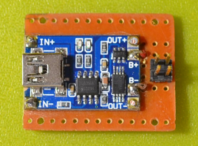
The solution was to:
- Use a protoboard with blank
sections between short horizontal tracks containing (undrilled) vertical
ground planes.
- Stake the IN+ and OUT+ (which
should not be conected) to separate horizontal tracks.
- Drill holes in the ground track
for the IN- and OUT- (which should be connected).
- Disconnect a pair of horizontal
tracks at the output end and mount the headers between them (a
double-row header was used for stability)
- Run wires through holes in the
protoboard from B+ and B- to the underside of the board for the headers.
The stakes are tinned copy wire recovered from a power supply transformer
with the varnish scraped away. The ground track on the copper side
of the protoboard runs midway along the gap between the sets of horizontal
tracks, which works out to exactly match the width of the holes in the
module. The IN- and OUT- are connected on the module, so the
connection through the ground track is just an extra precaution. This
example is intended for stand-alone charging only, so OUT+ and OUT- are
not brought out to any external connector.
B+ and B- are connected by hookup wire brought in through holes from the
underside of the header pins. This is easier than trying to stake
them (considering that they don't line up precisely with any holes) and
then running a connection on the underside.
Mounting
 Holes
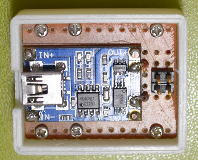
for the mounting screws in the unused vertical rows are drilled out to a
slightly larger size. The case is a simple rectangle to match the
protoboard, with two rails run along the base at the sides for
screws. The case is so small that it was printed with 100% infill
and the screw holes drilled after the board is pressed into the case. The
image shows an additional pair of screws added adjacent to the end of the
USB connector, to ensure a solid mounting at that end.
The lid is a simple cap with a cutout to allow access to the header pins.
Note that the cutout for the USB connector seems to suit most micro cables
because they have the housing set back from the insert by the case wall
width of 2mm. This places the cable housing flush with the end of the
case.
In Use
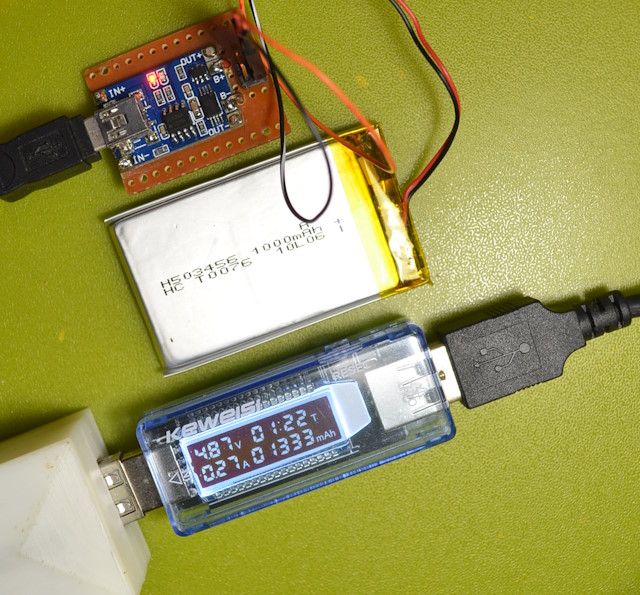
 The
arrangement for using the module for charging a small 1000mAh LiPo
battery.
Completed

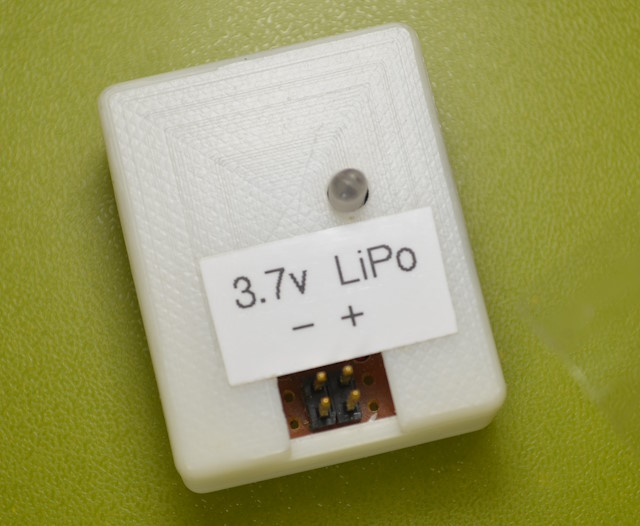
The completed unit with adhesive label. A short section of
transparent plastic rod (a left over sprue from a model kit) is placed
over the two LEDS and protrudes through a hole in the cap so the light is
visible. The space allowed either side of the header strip is there
because some of the connectors are 3 pins wide (for consistency with
multi-cell batteries that have a balance wire) even though only two are
used.

 Holes
for the mounting screws in the unused vertical rows are drilled out to a
slightly larger size. The case is a simple rectangle to match the
protoboard, with two rails run along the base at the sides for
screws. The case is so small that it was printed with 100% infill
and the screw holes drilled after the board is pressed into the case. The
image shows an additional pair of screws added adjacent to the end of the
USB connector, to ensure a solid mounting at that end.
 The
arrangement for using the module for charging a small 1000mAh LiPo
battery.
