LCD Clock
A clock module with a 16x2 LCD, temperature sensor and backlight control,
driven by a Nano. This is a proof-of-concept project and might
never be built..
The circuit was originally mocked up in order to demonstrate scrolling
the LCD display, but this turned out to be unsuitable, as the persistence
of the LCD created a smudging effect that meant that the display was
almost unreadable at certain levels of brightness and contrast.
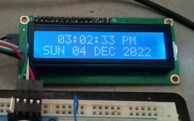
Instead, the second line of the display was set to alternate between the
date and the temperature.
Parts:
Arduino Nano
DS18B20 Module (Keyes). The module only adds a series resistor to the
DS18B20 chip.
DS1307 RTC Module
LDS A1050 or similar
BC337 NPN transistor, or similar.
Resistors - 1x1K, 2x10K
LCD display with I2C interface
Arduino Nano, USB cable to suit
Prototyping board and jumper wire
Schematic
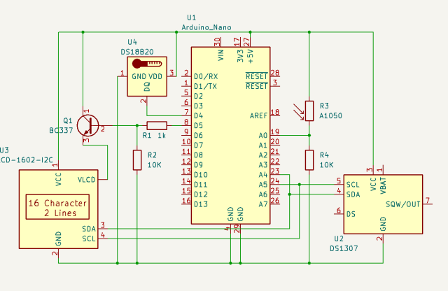 The
Nano I2C interface is wired through to the clock module and the LCD. The
DS18B20 uses a digital single-wire interface that is connected at pin 4,
while the analog reading from the LDR is connected at pin A0. The
brightness control for the LCD is driven from pin 5, through a small NPN
driver BC337.
The
Nano I2C interface is wired through to the clock module and the LCD. The
DS18B20 uses a digital single-wire interface that is connected at pin 4,
while the analog reading from the LDR is connected at pin A0. The
brightness control for the LCD is driven from pin 5, through a small NPN
driver BC337.
The LDR is used to dim the display when the ambient lighting falls below
a certain level. Only two levels of adjustment are provided, but it
would be easy to extend the adjustment to multiple levels.
.
Assembly
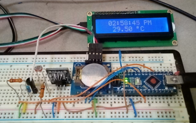
The parts are assembled on a piece of socketed prototyping board.
The layout would transfer to a soldered board with pretty much the same
payout, using the rails for ground and power and wired interconnects for
the signals.
Note the large red dot on the Nano. This has been added to indicate
that this device must be configured as 'Old Bootloader' in the Processor
Type setting in the IDE. These versions of the Nano devices are
perfectly functional, and are often available at a significant discount to
the newer versions. The only problem is that the device
characteristics are not marked, hence the addition of an identifier.
Code
 The
code is an amalgam of several sources, but is essentially the standard
Arduino code for each of the devices. The method of formatting the
numerical values is somewhat cryptic, but is justified in this application
by the simplicity compared with multiple 'if' statements. The LDR
value for switching to dim mode was derived by experiment and will change
with device used and the required brightness. It is possible, of
course, to set the 'bright' setting to something less than 255. The method
of alternating between date and temperature is simple but effective,
although it is technically incorrect at the rollover for the minute. Note
that the size of each array element in the day and month name arrays is 4,
not 3, in order to allow for the trailing zero which is required.
There is code provided in several places which does not allow for this
extra character and therefore creates strange program errors. Note also
that the LCD is not cleared between updates - this is to avoid blinking of
the display. Debugging prints to console are included but disabled,
but console initialisation and monitoring for the date/time setting
function ('u') is functional.
The
code is an amalgam of several sources, but is essentially the standard
Arduino code for each of the devices. The method of formatting the
numerical values is somewhat cryptic, but is justified in this application
by the simplicity compared with multiple 'if' statements. The LDR
value for switching to dim mode was derived by experiment and will change
with device used and the required brightness. It is possible, of
course, to set the 'bright' setting to something less than 255. The method
of alternating between date and temperature is simple but effective,
although it is technically incorrect at the rollover for the minute. Note
that the size of each array element in the day and month name arrays is 4,
not 3, in order to allow for the trailing zero which is required.
There is code provided in several places which does not allow for this
extra character and therefore creates strange program errors. Note also
that the LCD is not cleared between updates - this is to avoid blinking of
the display. Debugging prints to console are included but disabled,
but console initialisation and monitoring for the date/time setting
function ('u') is functional.
// Real Time Clock with LCD Display.

        // RTC I2C at 0x68

        // EEProm I2C at 0x50

        // LCD I2C at 0x27

        // DS18B20 at Pin 4

        // Photoresistor at pin A0

        // LCD LED backlight control at pin 5


        #include <Wire.h> // for I2C communication

        #include <LiquidCrystal_I2C.h> // for LCD

        #include <RTClib.h> // for RTC


        // DS18B20 single-wire temperature sensor library and object.

        #include <OneWire.h>

        int DS18S20_Pin = 4; //DS18S20 Signal pin

        OneWire ds(DS18S20_Pin);

        //


        LiquidCrystal_I2C lcd(0x27, 16, 2); // create LCD with I2C address 0x27,
        16 characters per line, 2 lines


        RTC_DS1307 rtc; // create rtc for the DS31307 RTC module, address is
        fixed at 0x68

        const int LCD_LED = 5; // LCD brightness control (PWM)


        /*

          function to update RTC time using user input

        */

        void updateRTC()

        {

          //lcd.clear(); // clear LCD display

          lcd.setCursor(0, 0);

          lcd.print("Edit Mode…");


          // ask user to enter new date and time


          const char txt[6][17] = { "year [4 - digit]", "month [1~12]",
        "day [1~31]",


        "hours [0~23]", "minutes [0~59]", "seconds [0~59]"


        };

          String str = "";

          long newDate[6];


          while (Serial.available()) {

            Serial.read(); // clear serial buffer

          }


          for (int i = 0; i < 6; i++) {


            Serial.print("Enter ");

            Serial.print(txt[i]);

            Serial.print(": ");


            while (!Serial.available()) {

              ; // wait for user input

            }


            str = Serial.readString(); // read user input

            newDate[i] = str.toInt(); // convert user input to
        number and save to array


            Serial.println(newDate[i]); // show user input

          }


          // update RTC

          rtc.adjust(DateTime(newDate[0], newDate[1], newDate[2],
        newDate[3], newDate[4], newDate[5]));

          Serial.println("RTC Updated!");

        }


        //*************

        // Get temperature from DS18B20.

        // Replace as required for other sensors.

        float getTemp() {

          //returns the temperature from one DS18b20 in DEG Celsius

          byte data[12];

          byte addr[8];

          if ( !ds.search(addr)) {

            //no more sensors on chain, reset search

            ds.reset_search();

            return -1000;

          }

          if ( OneWire::crc8( addr, 7) != addr[7]) {

            Serial.println("CRC is not valid!");

            return -1000;

          }

          if ( addr[0] != 0x10 && addr[0] != 0x28) {

            Serial.print("Device is not recognized");

            return -1000;

          }

          ds.reset();

          ds.select(addr);

          ds.write(0x44, 1); // start conversion, with parasite power on at
        the end

          byte present = ds.reset();

          ds.select(addr);

          ds.write(0xBE); // Read Scratchpad

          for (int i = 0; i < 9; i++) { // we need 9 bytes

            data[i] = ds.read();

          }

          ds.reset_search();

          byte MSB = data[1];

          byte LSB = data[0];

          float tempRead = ((MSB << 8) | LSB); //using two's
        complement

          float TemperatureSum = tempRead / 16;


          return TemperatureSum;

        }

        //*********************


        /*

          function to update LCD text

        */

        void updateLCD()

        {

          /*

            create array to convert digit days to words:

            0 = Sunday | 4 = Thursday

            1 = Monday | 5 = Friday

            2 = Tuesday | 6 = Saturday

            3 = Wednesday |

          */

          const char dayInWords[7][4] = {"SUN", "MON", "TUE", "WED", "THU",
        "FRI", "SAT"};


          /*

            create array to convert digit months to words:

            1 = January | 6 = June

            2 = February | 7 = July

            3 = March | 8 = August

            4 = April | 9 = September

            5 = May | 10 = October

            6 = June | 11 = November

            7 = July | 12 = December

          */

          const char monthInWords[12][4] = {"JAN", "FEB", "MAR", "APR",
        "MAY", "JUN",


        "JUL", "AUG", "SEP", "OCT", "NOV", "DEC"


        };


          // get time and date from RTC and save in variables

          DateTime rtcTime = rtc.now();


          int ss = rtcTime.second();

          int mm = rtcTime.minute();

          int hh = rtcTime.twelveHour();

          int DD = rtcTime.dayOfTheWeek();

          int dd = rtcTime.day();

          int MM = rtcTime.month();

          int yyyy = rtcTime.year();


          // Get Temperature

          float tc = getTemp();

          // Serial.println(tc);


          // Get Light Value

          int lv = analogRead(A0);

          (lv > 800) ? analogWrite(LCD_LED, 255) : analogWrite(LCD_LED,
        64);

          // Serial.println(lv);


          // move LCD cursor to upper-left position

          lcd.setCursor(2, 0);


          // Create and display time string

          String msg = ((hh < 10) ? "0" : "") + String(hh) + ":"


        + ((mm < 10) ? "0" : "") + String(mm) + ":"


        + ((ss < 10) ? "0" : "") + String(ss) + " "


        + (rtcTime.isPM() ? "PM" : "AM")


        ;

          // Serial.println(msg);

          lcd.print(msg);


          // move LCD cursor to lower-left position

          lcd.setCursor(0, 1);


          // Create and display date or temp string

          if ((ss & 0x4) == 0) {

            msg = String(dayInWords[DD]) + " "

                  + ((dd < 10) ?
        "0" : "") + String(dd) + " "

                  +
        String(monthInWords[MM -1]) + " "

                  + String(yyyy)

                  ;

            // Serial.println(msg);

            lcd.print(msg);

          }

          else {

            lcd.setCursor(0, 1);

            msg = "   " + String(tc) + " " + char(223)
        + "C " + "    ";

            // Serial.println(msg);

            lcd.print(msg);

          }

        }


        void setup()

        {

          Serial.begin(9600); // initialize serial

          pinMode(LCD_LED, OUTPUT);


          lcd.init(); // initialize lcd

          lcd.backlight(); // switch-on lcd backlight


          rtc.begin(); // initialize rtc connection

        }


        void loop()

        {

          updateLCD(); // update LCD text

          delay(900);


          if (Serial.available()) {

            char input = Serial.read();

            if (input == 'u') updateRTC(); // update RTC time

          }

        }
