 The
circuit could hardly be simpler - the four Pro Mini output pins drive the
ULN2003 which drives the motor.
The
circuit could hardly be simpler - the four Pro Mini output pins drive the
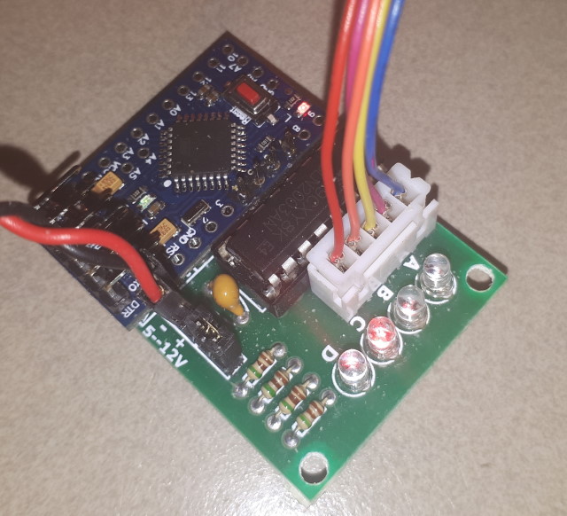
ULN2003 which drives the motor. This project is a slight re-working of a Thingiverse project. It is a clock in which the movement of the hands appears to be quite mysterious until you look closely and discover the mechanism.
The clock relies on the internal oscillator of the Arduino, so it is not as precise as a RTC module. However, the procedure for adjusting the time is trivial!
Arduino
Pro Mini
ULN 2003 Stepper Motor Driver
28BYJ-48 Stepper Motor
USB power adapter
3D printed components
Three 8mm x 3mm neodymium (neodym) magnets
(or Six 8mm x 1mm, which may be more available)
Assorted small self-tapping screws
Small nut and machine screw x 2 (optional)
The Pro Mini comes in two versions - 8MHz 3.3V or 16MHz 5V. Either
version would work - the 3.3V version was chosen simply because it was
available. The processor timing must be correct for the device
chosen. This will happen automatically in the Arduino IDE if the
processor is specified correctly (828P, 3.3V, 8MHz or 828P, 5V, 16MHz). If
it is specified incorrectly then the clock rate will be either twice or
half the correct value, clearly identifying the problem.
The
circuit could hardly be simpler - the four Pro Mini output pins drive the
ULN2003 which drives the motor.
The power can provided from a USB or similar plugpack. The Pro Mini is the 3.3V version, so the power is supplied to the RAW input. The 3.3v outputs of the Pro Mini are well within the operating range of the ULN 2003. The RAW input of the Pro Mini is being used, so the actual supply voltage is not critical - in this case a 5.8V adapter from an old phone was used.
The changes from the original design are:
Pro Mini, 3.3V, 8MHz instead of Nano 5V, 16MHz
Driver pins are D4, D5, D6, D7 instead of D2, D3, D4, D5
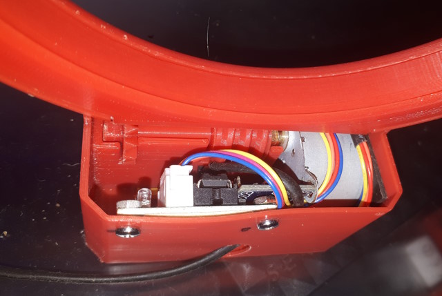
Pro Mini is soldered side-by-side with the driver module, instead of on
top
Combined module is mounted vertically on the rear panel.
In the original version the driver module pins are bent so that the Nano can be mounted across the top of the driver. With the Pro Mini the pins do not need to be bent, and the MCU can be mounted alongside the driver. This leaves the driver mounting holes accessible for two small screws and nuts to fix it through the back panel. The assembly should be positioned so that the edge of the Pro Mini is against the front plate of the motor, to prevent the motor twisting under the pressure of the pad behind it.
The power pins can be left installed, but they should be bent away from the main shaft so that the connector doesn't contact it. The power jumper should be installed, as this connects the motor power to the 5V supply. The 5V and GND are wired from the back of the driver board through to the Pro Mini. Note that this mounting leaves most of the Pro Mini pins accessible for other functions (such as buttons for fast forward and reverse, or a seconds blinking LED) if required.
The programming pins for the Pro Mini are right-angled headers mounted facing back over the board, so they are accessible with the MCU mounted against the rear panel.
After some experimenting I replaced the neodymium magnet in the hour hand with a rectangular magnet from the parts bin (probably from an old disk drive). I suspect that the original magnet was a cheap version that was not as strong as the one used in the original design. The replacement has worked well.
To set the time, simply lift the clock face out of the base and move the hands to the required time before reinserting it.

To set the clock rate it is important to follow a procedure, otherwise it
can become a slow and frustrating task. The procedure is similar to
a 'binary search'. Start with an arbitrary number (60000 is a good
choice). Determine if the clock is slow or fast, and make an
arbitrary adjustment. Determine the rate again and make another
adjustment. Keep track of the previous numbers Very
quickly you will have two numbers that must be the minimum and maximum for
the rate setting. As soon as you have this range, make your choice for the
new value about half way between the minimum and maximum. That gives
you a new minimum and maximum, so repeat the procedure until you hit the
right number. You can try to estimate whether the choice should be
to one side of the other of the half-way point, but it's probably not
worth the extra effort. The possible range will shrink very quickly
and you will be able to home in on the correct value. The example
for the above project was:
60000 Slow (Take a guess)
59900 Slow (Another guess)
59800 Fast (Start splitting the difference)
59850 Fast (Range is 59800 to 59900, adjust up)
59875 Slow (Range is 59800 to 59850, adjust down)
59862 Slow (Range is 59850 to 59875, adjust down)
59856 Slow (Range is 59850 to 59862, adjust down)
59853 Done!
The code is mostly as per the original article. However, as I couldn't follow some of the logic of the original I have changed it at the part that actually checks the time and determines whether or not the minute has incremented. The approach run uses the backlash in the system to provide the motor with a low-load startup at each tick.
The milliseconds per minute figure was determined by experiment. The nominal value is 60,000, but this assumes the Pro Mini oscillator is exactly as specified (8Mhz in this case). These oscillators are fairly stable, but not particularly precise, so experimenting to find the correct timing will probably be required. Decrease the value if the clock runs slow (fewer CPU millis() per second) or increase it if the clock runs fast (more CPU millis() per second).
Note that the clock will advance one minute on initial start. If the time is set by positioning the hands before applying power, this initial tick must be allowed for. Alternatively, remove the hands, rotate them to the correct time, wait for a tick and insert the hands.
// Hollow Clock Driver Code.
// See: https://www.thingiverse.com/thing:5636482

// Please tune the following value if the clock gains or loses.
// Theoretically, this value is 60000 but may need to be adjusted.
#define MILLIS_PER_MIN 59853 // milliseconds per a minute

// Motor and clock parameters
// 4096 * 90 / 12 = 30720
#define STEPS_PER_ROTATION 30720 // steps for a full turn of minute rotor at

// wait for a single step of stepper
int delaytime = 2;

// ports used to control the stepper motor (Pro Mini Version)
// if your motor rotates in the opposite direction,
// change the order as {7, 6, 5, 4};
int port[4] = {4, 5, 6, 7};

// sequence of stepper motor control
int seq[8][4] = {
  {  LOW, HIGH, HIGH,  LOW},
  {  LOW,  LOW, HIGH,  LOW},
  {  LOW,  LOW, HIGH, HIGH},
  {  LOW,  LOW,  LOW, HIGH},
  { HIGH,  LOW,  LOW, HIGH},
  { HIGH,  LOW,  LOW,  LOW},
  { HIGH, HIGH,  LOW,  LOW},
  {  LOW, HIGH,  LOW,  LOW}
};

void rotate(int step) {
  static int phase = 0;
  int i, j;
  int delta = (step > 0) ? 1 : 7;
  int dt = 20;

  step = (step > 0) ? step : -step;
  for(j = 0; j < step; j++) {
    phase = (phase + delta) % 8;
    for(i = 0; i < 4; i++) {
      digitalWrite(port[i], seq[phase][i]);
    }
    delay(dt);
    if(dt > delaytime) dt--;
  }
  // power cut
  for(i = 0; i < 4; i++) {
    digitalWrite(port[i], LOW);
  }
}

void setup() {
  pinMode(port[0], OUTPUT);
  pinMode(port[1], OUTPUT);
  pinMode(port[2], OUTPUT);
  pinMode(port[3], OUTPUT);
  rotate(-20); // for approach run
  rotate(20);  // approach run without heavy load
  rotate(STEPS_PER_ROTATION / 60);  // Rotate 1 minute
  //Serial.begin(9600);
}

void loop() {
  static long prev_min = 0, prev_pos = 0;
  long min;
  static long pos;

  min = millis() / MILLIS_PER_MIN;        // Get current ms value
  if(prev_min == min) {                   // If unchanged, then
    return;
  }
  prev_min = min;                         // Save current as previous
  pos = (STEPS_PER_ROTATION * min) / 60;  // Calculate new position
  if(pos - prev_pos > 0) {
    rotate(-20); // for approach run
    rotate(20);  // approach run without heavy load
    rotate(pos - prev_pos);
    prev_pos = pos;
    //Serial.print(pos);
    //Serial.print(" ");
    //Serial.print(millis());
    //Serial.print(" ");
    //Serial.println(min);
  }
}

This page last updated 18 August 2024
