A boost converter using the MT3608 module.
(For a step-down equivalent see below).
This project is mostly designing and printing the case - there is no custom circuitry involved, other than connectors for the module. However there are a few twists to the project.
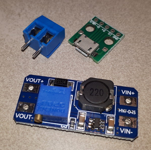
The boost converter is a widely-available module that takes an input of 2v - 24v and produces an output of 5v - 28v at about 2A. It features a multi-turn potentiometer for adjustment of the output voltage, but in this application it is used as a fixed-voltage boost converter for a number of 9v devices so they can be powered off a USB connector. To enable this it has been matched with a USB micro connector as the input. A screw connector is mounted for the output.
MICRO USB to DIP Adapter 5-pin female connector B type.
2-Way PCB-Mount Screw Terminal.

This application example uses a USB connector at the power source, so it is not likely to be used with more than 5v at more than a few hundred milliamps. However, if it is used at a higher voltage or current there are some special considerations that apply.
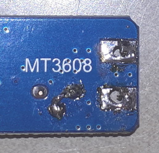
Many of the MT3608 modules have a fault that means they can easily be damaged when used as supplied. The fault is in the configuration of the multi-turn potentiometer used for adjusting the output voltage. The result is that the feedback input to the SDB628 chip can exceed the absolute maximum of 6V if the input is higher than 6V and the pot is turned towards the input end of its range. The image shows the link that needs to be added to the underside of the PCB for these versions in order to make the connection and ensure that the proper voltage is supplied to the feedback input of the chip. There are a number of videos on the 'net that explain the problem and show the fix. This problem is not an issue if the device is only ever powered from a USB 5v.
Some manufacturers may have caught up with the complaints about the design fault and fixed it, but it is difficult to tell from the on-line descriptions which ones are fixed and which are not. The items can be easily tested: the resistance from the wiper to ground should be zero. However there are other ways in which the circuit could be properly implemented, so that test might not be conclusive.
There is one range of modules which appears to be correctly fixed - they can be identified by having no thru-holes drilled for the input and output connections. But the advertising for this variant is often unchanged from the original images, so it is difficult to identify them on-line! See below for some images of how to adapt these versions to the screw connector used in this project.
Note that although the module is typically quoted as capable of supplying 2A, it will get very hot and possibly burn out if run continuously at that current without a heatsink. A sensible limit is about 1A. The devices used for this implementation are a digital ammeter, a transistor tester, and a timer for time-lapse photography: each one consumes much less than 1A. A suitable heatsink that will allow operation at more than about 1A is the type supplied with the A4988/DRV8825 style of stepper motor driver modules, mounted with suitable thermal paste or tape.
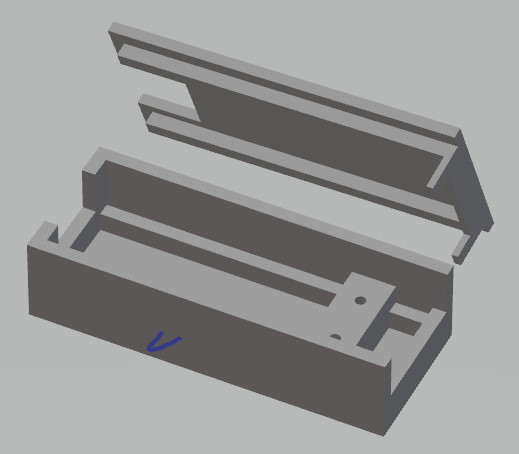
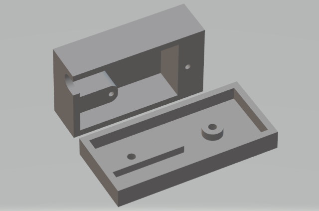
The module itself is simply a press fit onto side rails in the bottom of the base. Note that the image shows no provision for access to the voltage adjustment screw. For this application the voltage was going to be fixed. For applications where the voltage needs to be adjustable a hole in the side of the case would be added.
The surround for the USB connection has been attached to the lid. This makes it simpler to change, if needed, for a different style plug, in case the existing cutout is not large enough. It also simplifies printing the base because there is no overhang.
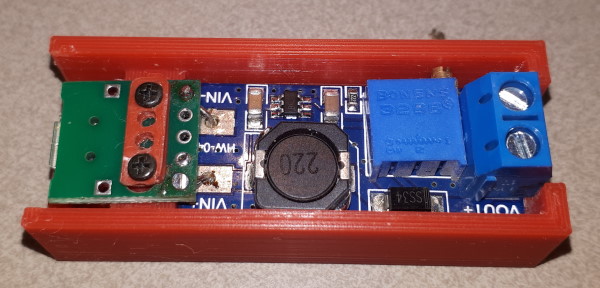
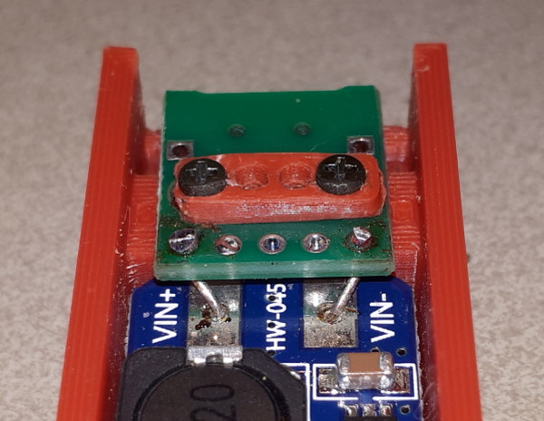
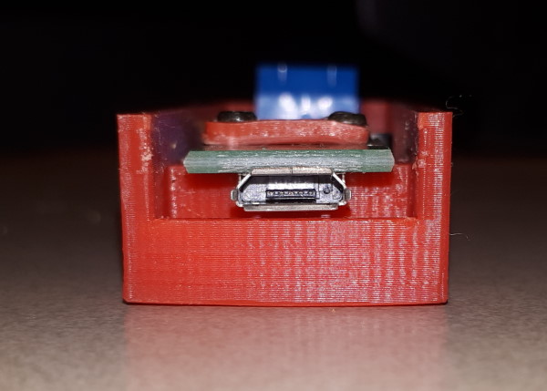
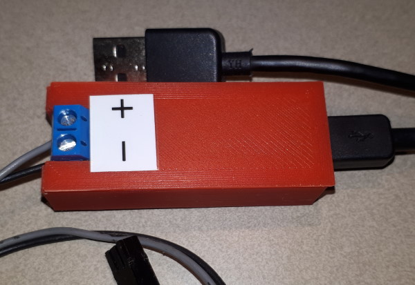
Install the module, screw the USB connector down to the bridge, and connect the device to be powered.
This power converter is designed to provide 3.3V from a USB 5v supply. It uses the 2307DN synchronous step-down converter. It is available as the 'Mini-360' module, with solder points for input and output, and a trimpot for voltage adjustment. Output is rated at up to 3A, but the module has no heatsinking and 2A is a more reasonable maximum. It is advertised as LM2596, which is pretty-much equivalent. The minimum input voltage of 4.75 makes it unsuitable for single-cell lithium batteries, but it is ideal for a USB supply. In this case it is used with a USB power pack for portable operation of ESP devices.
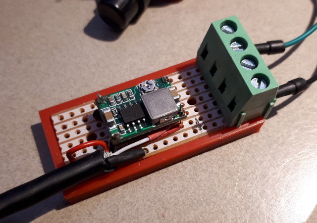
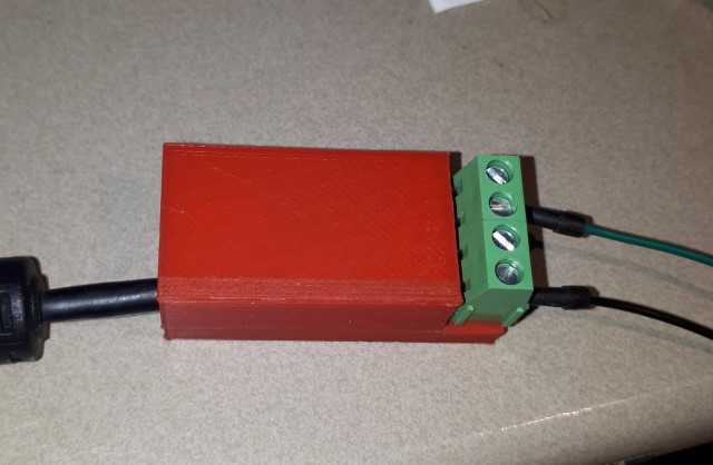
The module is mounted on a piece of strip-printed perforated prototyping board. The layout is simple, as the input and output are at opposite ends of the module. A single cut across all strips separates the input from the output - the USB cable is wired at one end and the screw terminals at the other. In this example the USB cable is recovered from an old PC mouse. Four screw terminals are mounted, to provide two positive connects and two grounds. The prototype board piece is longer than is actually required in order to allow for two screws to be fitted in line with the centre track, which is unused.
One small complication is that the module hole spacing is not a standard 0.1". To use it with the perforated prototyping board it is mounted on stakes with enough space to allow the pins to be bent to fit the holes. This space also aids airflow for cooling.
The USB data wires (green and white) are sealed with heatshrink tubing, and not just cut off short, to eliminate any risk of them shorting to the power traces. The USB cable is secured by having its shielding tied to the prototyping board, as well as being clamped by the lid of the case. The module is mounted on supports in the base and the lid is secured with screws fitted into countersunk holes from the base through to the lid. Once the unit is assembled it is adjusted to the required 3.3v output and the lid screwed down.
Note that the adjustment is very sensitive and needs to be done carefully. Once set it appears to stay fixed, but a drop of heat-gun glue might be advisable.
This page last updated 18 August 2024
