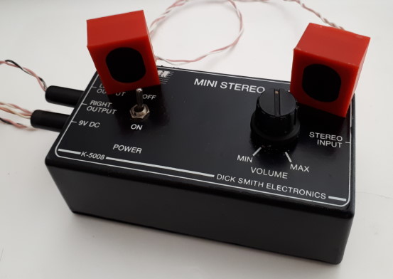
 The amplifier is used with a MP3
player and pair of speakers salvaged from some old headphones and
mounted into 3D-printed cases.
The amplifier is used with a MP3
player and pair of speakers salvaged from some old headphones and
mounted into 3D-printed cases.Upgrade a mini stereo amplifier kit with rechargeable battery power.
This project adds a rechargeable Li-ion battery and charging module to an old Dick Smith mini amplifier. The original was powered with a 9v plug pack, but works just fine with the 3.7v Li-ion. Recharging is though a USB port from any 5v USB source.
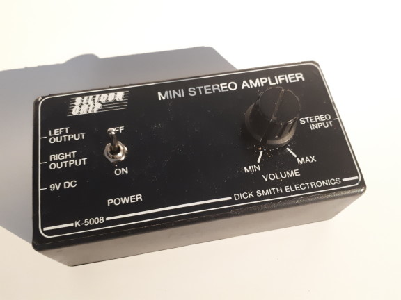 The
original kit is model K-5008 based on a Silicon Chip project. It is built
around the STMicro dual low-voltage amplifier IC. The stereo signal is
supplied at a 3.5mm stereo socket and the output is at two 3.5mm sockets. As
supplied, it is designed for a 9v plug-pack or battery, but the IC works to
about 1.8v, so the 3.7 to 4.2v from a Li-ion battery is quite suitable.
Output is a nominal 1W per channel, but that is at the maximum supply
voltage - it will be less with the battery power. The device as constructed
is used as a personal portable MP3 player, in conjunction with a pair of
miniature speakers and a MP3 player.
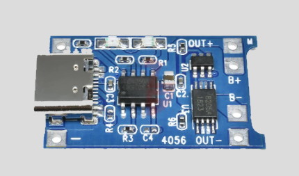 The components used in the upgrade are a Samsung 25R 18650-format Li-ion
battery, a matching battery holder, a charging module based on the TP4056
IC, and a USB connector board. Note that the charging module is the
type that allows for using the device while it is being charged.
This type has battery 'B' outputs that are separate from the outputs to
the load (the amplifier in this case). This meas that the
module can switch the supply from the battery to the USB 5v input when it
is being charged, and switch back to the battery when there is no charge
supply. This ensures that the load does not affect the
measured battery voltage while charging, so there is no risk of reading an
incorrect battery voltage and overcharging the battery. Modules
that do not have this capability should not have the load applied when
they are being charged. See below for an adjustment to the kit
construction than ensures that charging can only be done when the
amplifier is switched off.
The components used in the upgrade are a Samsung 25R 18650-format Li-ion
battery, a matching battery holder, a charging module based on the TP4056
IC, and a USB connector board. Note that the charging module is the
type that allows for using the device while it is being charged.
This type has battery 'B' outputs that are separate from the outputs to
the load (the amplifier in this case). This meas that the
module can switch the supply from the battery to the USB 5v input when it
is being charged, and switch back to the battery when there is no charge
supply. This ensures that the load does not affect the
measured battery voltage while charging, so there is no risk of reading an
incorrect battery voltage and overcharging the battery. Modules
that do not have this capability should not have the load applied when
they are being charged. See below for an adjustment to the kit
construction than ensures that charging can only be done when the
amplifier is switched off.The components include a separate USB connector board, even though the charging module is supplied with a connector.. This is because there is no simple way to mount the charging module in the existing case securely enough to ensure reliable connection of an external USB cable. If the charging module was being used in a custom-designed case then it would be possible to provide a secure mount for the module, and the additional USB connector would not be required.
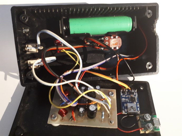 The original kit was constructed with the power switch,
external connectors and volume control mounted on the case front, and the
circuit board on the back. For the upgrade the battery holder has been
glued to the inside of the front cover, alongside the power switch and the
volume control, and the USB port and charger module mounted on the back,
alongside the circuit board. The USB port is wired through to
the inputs of the charger module, the battery ("B") terminals of the charger
are wired through to the battery holder, and the outputs from the charger
module are wired through to the amplifier, via the power switch for the
positive lead.
 The amplifier is used with a MP3
player and pair of speakers salvaged from some old headphones and
mounted into 3D-printed cases.
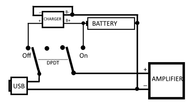 This wiring shows how the kit can be configured with a
two-pole two-position (DPDT) switch so that it will only charge when the
amplifier is switched off. This form of connection is required if
the charger module does not provide separate load and battery outputs,
such as those chargers that are designed for use only in dedicated battery
charging devices.
 This site was last updated 27th
September 2022.