ATX Bench Power Supply
An ATX power supply repurposed as a bench supply for 5V and 12V.
The project involves little more than just installing connectors into the
case, but there are some precautions that must be observed if the
conversion is going to work properly.
ATX Power Supply

The ATX power suply is pretty much standardized for both electrical and
physical features. Therefore the example used here will apply
to most power supplies that can be recovered from old ATX-format
PCs. Although it is here described as a bench power supply it will
only have fixed 5V and 12V supplies, and there is no voltage or current
control: It is simply a 5V and 12V supply at very high current.
In addition to general benchtop use, the conversion will also
apply to dedicated usage, such as with a model train layout.
The case is quite crowded, so this example has been restricted to tapping
into the 5V and 12V supplies. Adding 3.3V, -12V or (where available) -5V
terminals is possible, but the interior would become difficult to
access. Displays or level controls would have to be added
separately, and considering that the device would still be restricted to a
maximum 12V it would likely be preferable to start from scratch and build
a proper bench supply with a larger voltage range: the required components
are readily available.
Cautions
 The
conversion basically consists of cutting off the existing harness
connector, collecting the 5V, 12V and ground wires together into large
bundles and connecting them to screw terminals mounted on the front panel.
But there are several considerations that must be taken into account, some
of which may not be obvious.
The
conversion basically consists of cutting off the existing harness
connector, collecting the 5V, 12V and ground wires together into large
bundles and connecting them to screw terminals mounted on the front panel.
But there are several considerations that must be taken into account, some
of which may not be obvious.
Switching. If the PS is fitted with a power switch then
this can be used as the main switch. In that case the green power
control wire from the harness must be connected to ground. If the PS
has no power switch then one can be added. This can switch the
mains, so that the green wire is then earthed as above. A simpler
option is to have the mains input permanently live and the power switch
configured to switch the green wire to ground. This arrangement makes the
standby 5V available, which can be used for a mains power indicator.
Default Load. Like any high-current switch-mode
power supply, the unit might not switch on, or might provide poor
regulation, if there is no load attached. A bench supply is
likely to spend considerable time powered up but with no load attached. It
is critical that a dummy load is provided. Options include a
low-value high-wattage resistor, or a small incandescent lamp. It
can be applied across the 12V or 5V and can be anywhere from 1W to about
3W. The 'best' option depends on the particular unit, and there is
no easy way to find out what is best - experimenting is the only
method. But for most units the load is not critical. If
the unit fails to start, or clicks or turns itself off at any time, then
the load is insufficient. (Note: Many ATX power supplies can be recovered
from the junk pile by testing them with a load applied (and the green wire
earthed). Often a unit written off as faulty will prove to be
perfectly functional when properly loaded.)
3.3V Sense. The 3.3V sense wire is a brown or
orange wire connected to an orange (3.3V) wire at the plug end of the
harness. It will likely have a connection point on the PCB located
away from the other 3.3V wires, and will likely be a thinner wire than the
others on the harness. This wire MUST be connected to 3.3V,
regardless of whether or not 3.3V is being used in the supply.
Without this connection the voltage control circuit for 3.3V will see zero
volts on the sense, and might try to ramp up the 3.3 volt supply to bring
it up to spec. If that happens the power supply will explode.
Do not operate the unit without the 3.3V sense wire connected
to a 3.3V lead. Newer power supplies are usually
protected from this sort of over-regulation, but it should not be relied
on.
Also: Unused leads should have their ends
sealed with heatshrink. Just cutting them off short is likely to cause a
problem in the future.
Be sure to leave
enough leads out of the bundles connected to the terminals for the
purposes mentioned above.
The hole where
the cable bundle exited the enclosure should be filled with a suitable
plug. If a connector is added as mentioned above it could be mounted
on a plate that screws over the hole.
Construction
 The
important point about the construction is finding a suitable location for
the terminals and routing the cables from the PCB to the terminals.
The details will vary between units.
The
important point about the construction is finding a suitable location for
the terminals and routing the cables from the PCB to the terminals.
The details will vary between units.
For this example the considerations were:
- The fan took up almost all of the
lid, so nothing could be placed above the level of the heatsinks
- There was space for the terminals
behind the front panel, but they had to be placed towards the top to
make wiring access practical
- Cable routing for the terminals
is a mixture of straight to the front and round the back. Wires should
be cut to length: there is very little room for excess wire.
- Separate negative terminals were
provided with separate cabling: a single negative terminal, or two
terminals with one set of cabling would be acceptable alternatives if
space is a problem.
- There were two holes for
indicator LEDs already drilled at the bottom of the front panel. The
main PCB was already cut away immediately behind these holes, providing
space for a small protoboard for mounting the LEDs.
- The load resistor was fastened
across the ventilating mesh at the rear. This put it in the
cooling air-stream without any significant impact on the flow.
- Mounting points were not used for
the other connections (3.3V sense, power control): they were just
soldered together and wrapped in heatshrink.
- Unused 3.3V wiring was bundled
together and tied against the back panel, allowing for a possible future
expansion to include additional terminals.
The terminals used here are 4mm dual banana/screw terminals. The
spade connectors are crimped and soldered. About 5 wires is the
maximum they can accommodate, but that is ample. Note that
sufficient exposed end must be allowed - when twisted together the bundle
of bare wires becomes tapered, and it is easy to leave one or two short of
the crimped section. If crimping is used the wires must be twisted
- the crimping is not even across the width of the terminal. An
alternative is to leave them untwisted and solder without crimping. 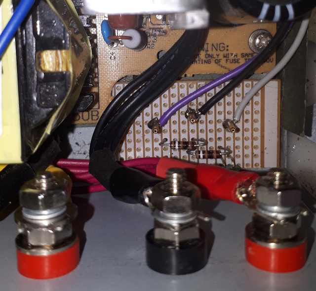
The image shows the mounting of the LEDs on their piece of protoboard at
the base of the front panel. Note that this board requires one of
the spare earth leads.
The image shows the load resistor clamped across the ventilation mesh at
the rear of the case. Note that this requires one of the spare 12v
wires plus one of the spare earth leads.

Indicators

The indicator LEDs are mounted with their resistors on a scrap of
perfboard. Stakes are then added for terminating the wires
from the harness. The module is then positioned with the LEDS protruding
through the holes already drilled in the front panel, and held in place
with a small dab of hot glue. This places it well out of the way of
the power terminals and their associated wiring.
The red LED is powered by the purple wire (+5V standby) and the green LED
is powered by the gray wire (power good).
A possible enhancement is to bring one +12V wire, the -12V (blue) wire
and one ground wire to a low-current 3-pin connector for use as a bipolar
supply. As a low current output, the connector would be small enough to
find space on the front panel.
