Ammeter Project
The objective of the project was to create a stand-alone ammeter that could
be used to check the current draw of devices such as DC motors, in
particular to enable adjustment of the stepper driver current setting when
the details of the motor were not known (which is often the case when using
motors recovered from old equipment). While I have several multimeters that
can measure current, I wanted a separate unit because I have destroyed too
many devices when forgetting to turn the multimeter back to voltage!
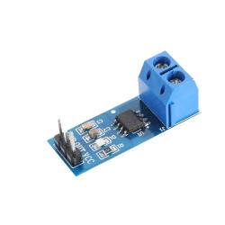
The ACS712 current sensor module uses a hall-effect device to measure
current. It is available in three configurations, with maximum rated current
of 5 Amps, 20 Amps and 30 Amps.The 5A version was selected for this project
as it provided the required range with the maximum available resolution.
This project uses this module in conjunction with an Arduino Pro Mini and a
128x64 OLED display to create a digital ammeter.
Measuring Current.
 The
ACS712 is a current sensing module that uses a low resistance shunt and a
hall-effect sensor to measure current. It interfaces to the Arduino
with an analog signal. The documentation for the ACS712 module
indicates that it only needs a connection to the Arduino and some
calculations in code to create the ammeter, but it turns out that the
process is not quite as simple as that.
The output of the module is a voltage that is proportional to the current
flowing through the device. The
module measures both AC and DC current, and for DC will report the current
as positive or negative. Therefore
the voltage output is centred around half of the module supply voltage. The
measured voltage represents amps per millivolt – for the 5-Amp device the
measurement is 0.185v per Amp. In order to convert this voltage to a current
reading the Arduino needs to know the supply voltage of the module, in order
to calculate the centre value and therefore the variance from this centre
value.
The Arduino has an ADC input available for measuring the supply voltage, but
this measurement depends, in turn, on knowing the supply voltage for the
Arduino. Whichever way it is arranged, a reference voltage seems to be
required.
The Arduino supply voltage is not suitable as a reference, as it can vary
from about 4.8v to a little over 5v, depending on where the nominal 5v is
being generated. The Arduino
ARef output cannot be used as it is not reliable at 5v if the Arduino supply
voltage dips below 5v, and it cannot be used at less than 5v as the ACS
module requires a supply of 5v. An external reference could be used, but the
circuitry becomes complex if it has to deal with a supply that might be less
than 5v. In each case the reference also has to deal with a varying load
from the ACS module.
This project avoids the problem of a reference voltage by using the nominal
5v supply and providing a calibration routine to adjust the calculation of
the module output voltage to the actual module supply voltage, without any
attempt to determine the absolute voltages.
The calibration occurs automatically at start up (on the assumption that no
load is connected to the ACS module) and whenever the user presses the
calibration button. This
procedure gives a reading that is good to within about 25mA, as far as I can
measure with typical hobbyist equipment. There has been comment that
the ACS module is not very accurate, but this is likely due to a failure to
include this calibration procedure.
The maximum resolution that is theoretically available can be calculated
from the available technical data. The
Arduino 10-bit ADC can create 1024 different values, with some uncertainty
at the 10th bit. At a supply voltage of 5v this translates to
about 5mv per count. A 5-Amp
module produces a voltage variation of 185mv per amp, so the Arduino can
detect about 37 counts per amp, or about 27mA, which agrees with the
measured results.
PARTS USED.
Arduino Pro Mini. I chose the Pro over the Nano because
I do not expect to be re-programming it and the USB interface could not be
justified. I have positioned it so that I can access the serial input pins
if required.
ACS712 current sensor module. Any
of the available variations of maximum rated amperage will do, but note
that the resolution is less at higher rated amps. The code provided
assumes the 5A version.
128x64 OLED display with I2C interface.
On/Off button. Salvaged from an old PC.
Momentary push button. Salvaged from an old PC.
Hookup wire and a scrap of perfboard.
9v Battery with clip and leads.
3D printed case with 3 3mm screws and knurled inserts.
DISPLAY.
The OLED display is a common, easily available item. For this project
I mounted it in a frame, because the unit is very fragile and it was going
to be subject to a lot of handling. I also inserted headers, but this
is not necessary - it is just as easy to solder the hookup wires direct to
the device. These displays are also available with an ISP interface -
either would work for this project, but the extra speed of ISP is not
required.
THE CIRCUIT
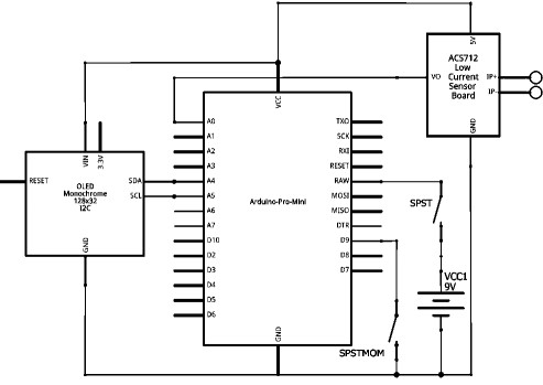
 The 9v battery power is provided via the on/off switch to
VRaw of the Pro. Vcc from the Pro is distributed to the OLED and the
ACS. The ACS output is connected to analog input AO of the Pro, and
the SDA/SCL inputs for the OLED are driven from pins A4/A5 respectively of
the Pro. The calibration switch is a momentary connection of digital
pin 9 of the Pro to ground. The grounds of the three devices are all
tied to battery ground.
THE PROTOTYPE
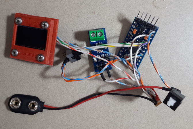
 After getting a
suitable layout for the components I wired everything together. The
hookup wire came from an old parallel printer cable. This wire is
easily tinned and soldered, the covering is very heat resistant, it is quite
flexible, and the multitude of colours means that the wire can indicate the
function of the connection, reducing the risk of mistakes. I used a
small strip of perfboard for the +5v and Gnd busses - the only parts of the
circuit with multiple connections.
Note that a prototyping board was not used for this project because the
components sit at different heights relative to the top surface, so it
would have been difficult to get everything at the correct level if they
were soldered to a single board.
The cover for the OLED was sourced from Thingiverse and scaled to
suit. There are many different sizes of OLED, so some experimenting
will probably be required to get just the right size. When adjusted
correctly the frame clamps the mounting surfaces between the front and
rear sections, without imposing any pressure against either the OLED
surface or the module substrate.
THE CASE
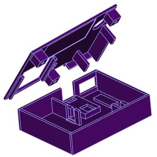
 With the layout confirmed
I designed a case to suit. Only the ACS module and the perfboard
strip have mounting holes, so everything else sits on an offset on the
bottom of the case, and is positioned by dividing pieces or by the cutout
in the lid.
There is a cutout for the Pro programming pins
connections at the back, with a cover plate that can be pressed into place
to conceal them.
ASSEMBLED
 With the components
inserted into the base a final test can be run before screwing on the lid. A
small piece of foam can be inserted at the front of the battery to stop it
moving, however it is actually held quite firmly between the lid and the
base. Note that not all ACS 712 modules include mounting holes to
allow it to be screwed down to the base - the terminals can require some
force to loosen if they have been overtightened, so a module that can be
firmly screwed down is probably preferred.
COMPLETED
 The completed unit. The back
screws onto the face using 3off 3mm screws into knurled inserts set into
holes molded into the lid supports. Some components are glued to their
bases using a hot glue gun to make assembly easier. The OLED sits in a
frame that fits into the cutout in the lid and is supported on risers in the
base. The supports for the Pro and ACS are shaped to allow for the
solder points that extrude from the underside. The two switches straddle
their supports so that the pins help to locate them securely.
CODE
The code for the ammeter is not complex, but it does
include a calculation to allow for calibration. This calculation occurs at
startup, so there is an assumption that no current source is attached the
the ACS terminals when the Arduino initialises.
The calibration code also executes whenever the user
presses the calibration button. This should only be done when there
is no load across the ACS terminals. This is not really required, as it is
almost as easy to turn the unit off and turn it on again, but it is
available as a quick check that the battery voltage has not changed
significantly.
The code uses the Ascii and AsciiWire versions of the
SSD1306 OLED libraries. These libraries provide all the
functionality that the application needs with much less overhead than the
standard libraries. The standard libraries could be substituted with a few
simple and obvious changes to the code (although some juggling might be
required to get the display laid out just right).
Confirm that the I2C address for your OLED is
correct. Adjust the number of samples if required (above about 100
it makes very little difference).
#include <Wire.h>
#include <SSD1306Ascii.h>
#include <SSD1306AsciiWire.h>

// OLED I2C address
#define I2C_ADDRESS 0x3C
SSD1306AsciiWire display;

boolean startup = true; // Flag to indicate auto calibrate
const int acsIn = A0;   // Analog input for ACS reading
const int btnIn = 9;    // Digital input for button press (active low).

void setup() {
  Wire.begin();
  Wire.setClock(400000L); // Adjust to suit OLED, if required.

  pinMode(btnIn, INPUT_PULLUP);
  pinMode(acsIn, INPUT);
  //1 Serial.begin(9600); //Start Serial Monitor to display current read value on Serial monitor
  display.begin(&Adafruit128x64, I2C_ADDRESS);

  display.setFont(fixed_bold10x15);
  display.clear();
  display.println();
  display.setLetterSpacing(2);
  display.println(F("DIGITAL"));
  display.print(F("   AMMETER"));
  display.setFont(Adafruit5x7);
  delay(1000); // Pause for 2 seconds
}

float cNominal = 1024.0;  // ADC count max
float cCentre = 512.0;    // ADC count centre (zero amps)
float vpc = 0;            // Volts per count

void loop() {

  unsigned int x = 0;
  float vInput = 0.0, nSamples = 0.0, vAverage = 0.0, vAdjusted = 0.0, aCalculated;

  for (int x = 0; x < 150; x++) {   //Get 150 samples.
    vInput = analogRead(acsIn);     //Read current sensor values.
    nSamples = nSamples + vInput;   //Accumulate sample values.
    delay (5);                      // Required ADC settling time.
  }
  vAverage = nSamples / 150.0;      // Calculate average value.

  //vpc is the assumed supply Vcc.  The ADC value is referenced to this voltage.
  //You must change the offset according to the input voltage
  //0.185 (185mV) is output voltage change for 1A current ACS712-05 ( 5 Amp).
  //0.100 (100mV) is output voltage change for 1A current ACS712-20 (20 Amp).
  //0.066 (66mV) is output voltage change for 1A current ACS712-30 (30 Amp).

  vpc = 5.00 / cNominal;    // millivolts per ADC count. Adjust if Vcc is not 5v.
  vAdjusted = (vAverage - cCentre) * +vpc; // Volts = Count * Volts per count.
  aCalculated = vAdjusted / 0.185;         // Amps = Volts / Volts per Amp.

  // Re-calculate zero amps reading and max count at startup and at button press.
  if ((digitalRead(btnIn) == LOW) || startup) {
    cCentre = vAverage;
    cNominal = cCentre * 2.0;
    startup = false;
  }

  display.clear();
  display.setFont(System5x7);
  display.println(String(cNominal, 3) +  ' ' + String(vAverage, 2));
  //display.println();
  display.setRow(2);
  display.setFont(ZevvPeep8x16);
  display.set2X();  // Double-size font
  if (aCalculated >= 0.0) {
    display.print("  " + String(aCalculated, 3));
  }
  else {
    display.print(" " + String(aCalculated, 3));
  }
  display.set1X();  // Standard-size font.
  display.setCursor(98,6);
  display.println("Amps");

  delay(50);
}
This site was last updated 18th August 2024.

 With the layout confirmed
I designed a case to suit. Only the ACS module and the perfboard
strip have mounting holes, so everything else sits on an offset on the
bottom of the case, and is positioned by dividing pieces or by the cutout
in the lid.
 The
ACS712 is a current sensing module that uses a low resistance shunt and a
hall-effect sensor to measure current. It interfaces to the Arduino
with an analog signal. The documentation for the ACS712 module
indicates that it only needs a connection to the Arduino and some
calculations in code to create the ammeter, but it turns out that the
process is not quite as simple as that.
  The 9v battery power is provided via the on/off switch to
VRaw of the Pro. Vcc from the Pro is distributed to the OLED and the
ACS. The ACS output is connected to analog input AO of the Pro, and
the SDA/SCL inputs for the OLED are driven from pins A4/A5 respectively of
the Pro. The calibration switch is a momentary connection of digital
pin 9 of the Pro to ground. The grounds of the three devices are all
tied to battery ground.
  After getting a
suitable layout for the components I wired everything together. The
hookup wire came from an old parallel printer cable. This wire is
easily tinned and soldered, the covering is very heat resistant, it is quite
flexible, and the multitude of colours means that the wire can indicate the
function of the connection, reducing the risk of mistakes. I used a
small strip of perfboard for the +5v and Gnd busses - the only parts of the
circuit with multiple connections.
 With the components
inserted into the base a final test can be run before screwing on the lid. A
small piece of foam can be inserted at the front of the battery to stop it
moving, however it is actually held quite firmly between the lid and the
base. Note that not all ACS 712 modules include mounting holes to
allow it to be screwed down to the base - the terminals can require some
force to loosen if they have been overtightened, so a module that can be
firmly screwed down is probably preferred.
 The completed unit. The back
screws onto the face using 3off 3mm screws into knurled inserts set into
holes molded into the lid supports. Some components are glued to their
bases using a hot glue gun to make assembly easier. The OLED sits in a
frame that fits into the cutout in the lid and is supported on risers in the
base. The supports for the Pro and ACS are shaped to allow for the
solder points that extrude from the underside. The two switches straddle
their supports so that the pins help to locate them securely.