Motor / Servo Bench Tester
A project that uses an Arduino UNO and an old motor driver shield to
create a single test point for servos, DC motors and stepper motors. The
device supports control for one stepper, two DC motors and two servos.
Parts
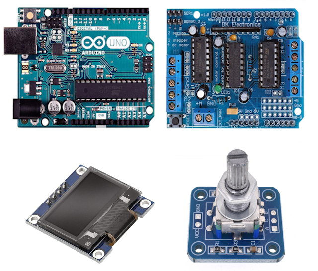 Arduino
UNO. Standard format, but the exact variant doesn't matter. In this
case it happened to be a unit that had a failed Mega16U2, so it was no
longer usable as a development board, but quite suitable as a dedicated
device.
Motor Driver Shield V1. DK Electronics. This is also
marketed as the Funduino L293D Motor Shield. This shield is now
regarded as obsolete, so finding a dedicated task that it could be
assigned to was a worthwhile usage. The motor, servo and power connections
are made through the shield pins, while the display, encoder and pot
connections are soldered to the unused pins using the small prototyping
area.
OLED, 0.96" Mono 128x64 I2C. Small, but
adequate for the limited user interaction implemented in the device.
Rotary Encoder with switch. Used to navigate the
menu displayed on the OLED. The number of ticks per revolution
doesn't matter as it is only used for rotation, not positioning.
Note that this item should be selected carefully, as the modules vary
considerably in ease of usage - see comments below.
Potentiomenter - 5K Ohm, linear. Used for
controlling the motor speeds and setting some other test values. Note that
the resistance could be anything between about 2K Ohm and 20K Ohm.
Also light hookup wire, solder
Enclosure:
Faceplate
Case
Knobs (x2)
4 x 4MM mounting screws
2.5mm x 24mm metal shaft with knob and keeper (Optional - Reset).
Note: The rotary encoder modules that are available vary widely, and some
are very difficult to get to work correctly. The one used for this project
included resistor/capacitor debouncing but some debounce was also
implemented in the code. The switch is not wired through to any
terminals by default - this allows maximum flexibility for switch usage.
In this case it is used as a single pole NO switch to ground, so a link
from one terminal to ground was added to the module. The switch is
not polarized.
The shield will drive two bipolar or unipolar stepper motors, four DC
motors and two 5V servos. The software for this project limits
the usage to one bipolar motor, two DC motors and two 5V servos. Provision
is included for an external supply for the motor, which is the recommeded
arrangement. With an external motor supply the 'PWR' jumper must be
removed. The alternative is to install the jumper and power
the motor from the Arduino power - in this case external power must not be
connected. The servos are powered from teh Arduino 5V, so onmly
small servos are supported.
Construction
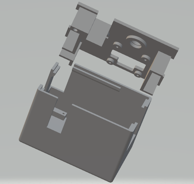 The shield
sits on top of the UNO, while the display, encoder and pot are fastened to
the faceplate of the case. The full GPIO usage is:
D0 Unused (UART RX)
D1 Unused (UART TX)
D2 *Encoder A
D3 DC Motor #2
D4 Motor Control
D5 Stepper
D6 Stepper
D7 Motor Control
D8 Motor Control
D9 Servo #1
D10 Servo #2
D11 DC Motor #1
D12 Motor Control
D13 Unused (LED)
A0 *Potentiometer
A1 *Encoder B
A2 *Encoder Switch
A3 Unused
A4 *SDA (Display)
A5 *SCK (Display)
* Wired to the component on the faceplate ( also +5V and GND). All
other pins are connected through the shield headers. A3 or D13 could be
used for a beeper to indicate a switch press, but has not been implemented
in this project.
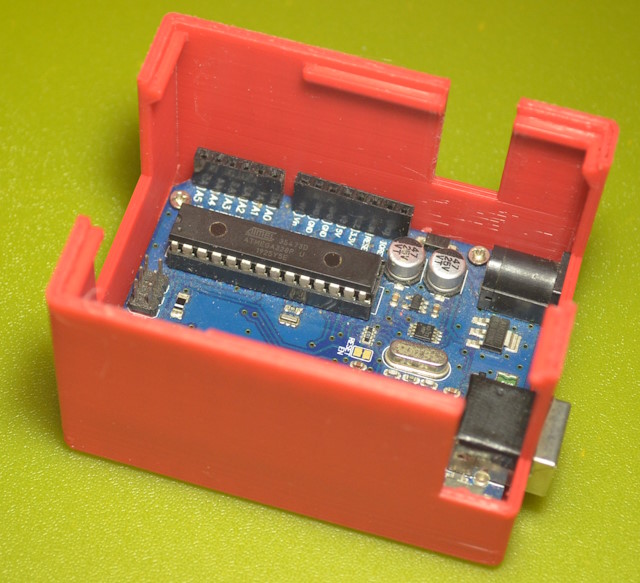
The case consists of two parts - a faceplate and a case. The
faceplate sits down into the case on ledges molded into the sides close to
the top. No fastenings are used. This simplifies the process
of mounting the components to the faceplate while they are wired to the
shield. The display is set in a frame to ensure that it can be fastened
down to the faceplate without putting pressure on the surface of the
OLED. The pot and encoder wiring is soldered onto the shield, while
the display is connected by a header (there is sufficient space for the
header above that portion of the shield).
There is a gap in the faceplate supports to allow the UNO to be slid in
from the end. The shield slips in sideways.
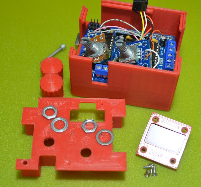
There is a tube for a 2.5mm pin to run down from the faceplate to the
surface of the reset button. A generic plastic button is pushed onto the
top and a small keeper can be pushed on at the bottom to prevent the shaft
from slipping out.
The knobs for the pot and encoder can be 3D-printed if suitable knobs are
not provided with the devices.
Software
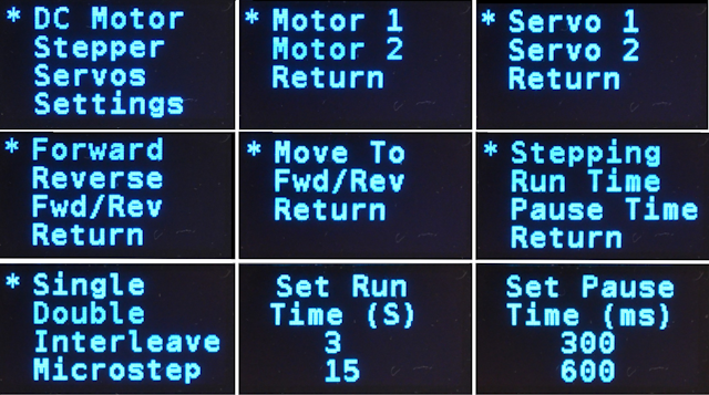
 The software is reasonably simple, as it is a series of menus and
actions. A state machine is used, with the machine state
corresponding to the current menu or operation. Menu options are
highlighted with an asterisk and the selection is changed by rotating the
encoder, and selected by pressing the encoder switch. Selection can be by
CW or CCW rotation. Each menu has a 'Return' option at the bottom.
Because the shield uses most of the GPIO pins, only one interrupt pin was
available. This has been used for the encoder A (leading)
output. This means that it is difficult to use the encoder switch to
signal the end of a running procedure (such as running a motor while
monitoring the pot to set the speed). Therefore movement of the
encoder is used to terminate these functions. This is not consistent
with other similar devices, but actually turns out to be very easy to use.
The encoder switch is used to indicate a menu selection.
The available tests are:
DC Motor (Motor 1, Motor 2)
Forward. Run the motor forward. Speed is set by the pot.
Reverse. Run the motor in reverse. Speed is set by the pot.
Fwd/Rev. Run the motor forward then in reverse. Run time in each
direction is controlled by the 'Run Time' setting and the pause when the
direction changes is controlled by the 'Pause Time' setting.
Stepper Motor (Motor 2)
Forward. Run the motor forward. Speed is set by the pot.
Reverse. Run the motor in reverse. Speed is set by the pot.
Fwd/Rev. Run the motor forward then in reverse. Run time in each
direction is controlled by the 'Run Time' setting and the pause when
the direction changes is controlled by the 'Pause Time' setting.
Servos (Servo 1, Servo 2)
Move To. Move the servo to a position (0 to 180) as set by the pot.
Fwd/Rev. Move the servo 0 to 180 and back. The pause time when the
direction changes is controlled by the 'Pause' setting.
In each case the test is terminated by moving the encoder.
The available settings are:
Stepping. The step mode used for the stepper tests - Single, Double,
Interleaved or Microstep. The default microstep value is 16. Press the
encoder button to select.
Run Time. The time (in seconds) that the motor runs forward or backward in
the 'Fwd/Rev' tests.
Pause Time. The time (in ms) that the motor or servo pauses when it
changes direction in the 'Fwd/Rev' tests.
For the time settings, the current value of the setting is displayed
together with the proposed value, which is set using the pot. The
settings procedure is cancelled by turning the encoder CCW, or confirmed
by turning it CW.


 Arduino
UNO. Standard format, but the exact variant doesn't matter. In this
case it happened to be a unit that had a failed Mega16U2, so it was no
longer usable as a development board, but quite suitable as a dedicated
device.
 The shield
sits on top of the UNO, while the display, encoder and pot are fastened to
the faceplate of the case. The full GPIO usage is:
 The software is reasonably simple, as it is a series of menus and
actions. A state machine is used, with the machine state
corresponding to the current menu or operation. Menu options are
highlighted with an asterisk and the selection is changed by rotating the
encoder, and selected by pressing the encoder switch. Selection can be by
CW or CCW rotation. Each menu has a 'Return' option at the bottom.
