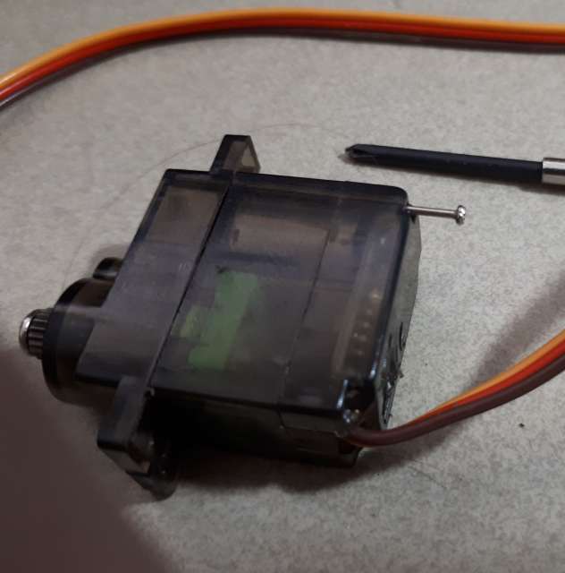
This description shows how to convert a dead servo into a useful
low-voltage high-torque motor.
If a servo is driven with excessive voltage then it is likely that the logic board will fail before the motor burns out. If that is what happens then it is possible to bypass the logic board and re-purpose the servo as a motor. If the failure is in the motor or in the gear mechanism, then this procedure will not work.
This example is for a MG90S servo, but the same procedure should work for any servo.
There are a number of tutorials that have been published on how to convert a servo into a motor. However the usual description for the process requires a working logic board in the servo: the servo can then be driven directly from a PWM output on the Arduino. This description applies to a servo with a dead logic board, and the motor can be driven only from a DC motor driver that supplies full current for the motor. The motor speed can be controlled (as for any DC motor) using PWM to simulate a variable voltage.

SG90 servo motor or similar that has been abused so that the controller is dead. All servos follow the same basic construction, but not all have accessible components. The SG90 is the smallest and cheapest that is in general use. It makes a very effective small slow-speed high-torque motor (due to the in-built gearing), with convenient mounting tabs.
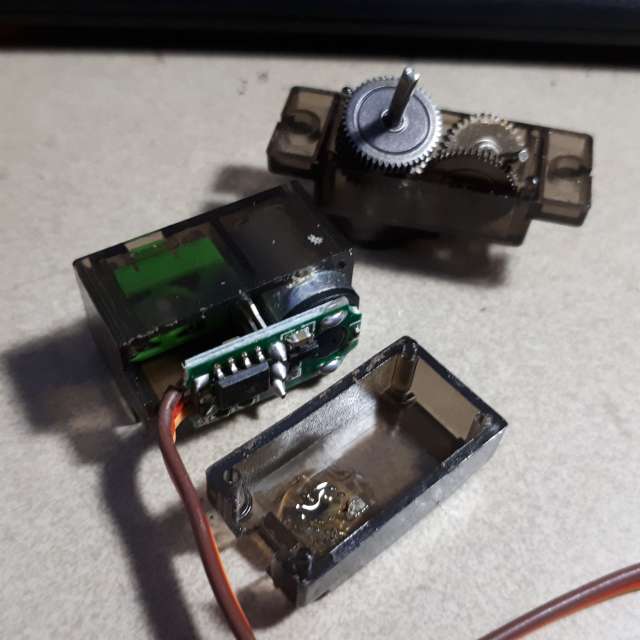
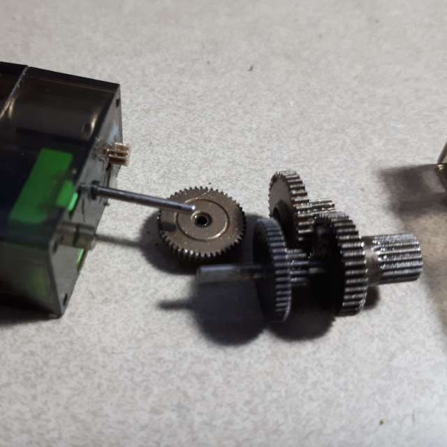
Carefully slip the gears off the motor shaft and the pot shaft. They can be pretty much held in their original positions to make re-assembly easier, but it is worth taking a photo before disassembly to show the arrangement. If you do disassemble the gear train it would be worth cleaning the gears and shafts so that everything runs as smoothly as possible.
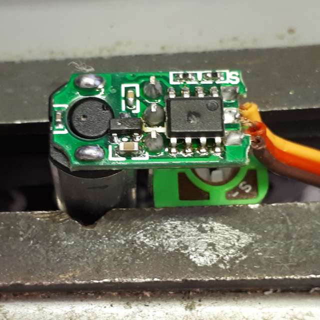
Slide the motor assembly out of the centre section of the case. The retaining mechanism varies slightly between manufacturers, but the usual arrangement is a pair of small clips holding the potentiometer assembly to the top face of the centre section. Mount the assembly in a fixture and unsolder (or just cut) the three leads.

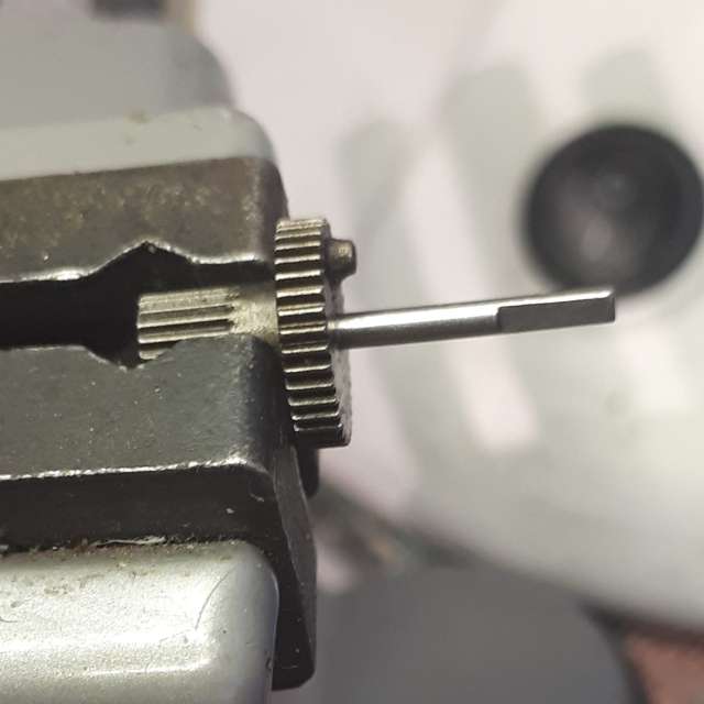
Mount the gear in a fixture and grind the stop off with a small cutoff disk in a high speed grinder. A flat file could also be used to remove the stop.
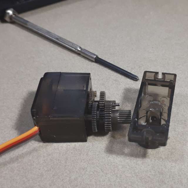
Note: This example is for a servo that has metal gears. Cheaper versions have plastic gears, but they are identical. You can swap gear sets around so that the best gear set is on the device that needs it most.
This page last updated 18 August 2024
